Power-over-Ethernet (PoE) delivers power to remote powered devices (PDs) over twisted-pair Ethernet cables up to 100 meters long. Over time, the standard has evolved and can now deliver up to 71W, making it useful for a wide variety of applications, including network routers and repeaters, VoIP phones, IP security cameras, wireless and Bluetooth access points, laptop and tablet charging systems, LED lighting and controllers, and a variety of building automation devices. This FAQ begins with an overview of how The IEEE 802.3 working group defines PoE as part of the Ethernet standard. It then looks at the cabling needed to implement PoE and then discusses the variety of magnetic components required by PoE installations. Magnetics are required to provide the isolation, filtering, and power conversion functions needed to ensure that the primary mission of Ethernet, delivering high-speed and robust data connectivity, is not compromised by the added function of power delivery.
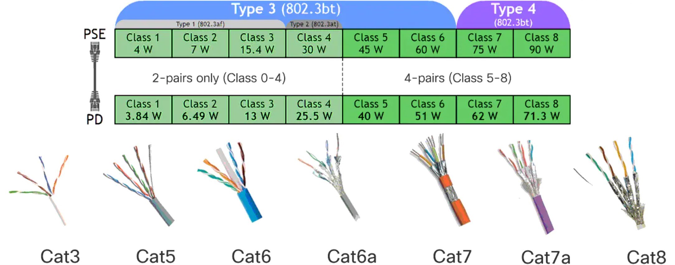
PoE is designed to operate with a nominal voltage of 48Vdc (36 to 57 Vdc), increasing to 73Vdc in some implementations. The standards define both the communication protocols for device identification and the physical requirements for PoE systems. PoE has evolved to address the desire for higher power levels to be delivered to PDs:
- IEEE 802.3af–2003 up to 12.95 W
- IEEE 802.3at–2009 up to 25.5 W (2–pairs, medium power)
- IEEE 802.3at–2009 up to 51 W (4–pairs, high power)
- IEEE 802.3bt–2018 up to 71 W (also called 4PPoE)
Each new revision is backward compatible with earlier standards and sets the maximum power delivered to a PD, taking into account the power loss over a 100-meter-long cable (Figure 1). Cabling requirements also evolved with the increases in power delivery. Cat 5 cabling is the minimum requirement for Type 3 (60W) and Type 4 (90W) PoE.
PoE equipment is categorized by its function in the system:
- Power Sourcing Equipment (PSE) provides power over the Ethernet cable to a powered device, including endspan equipment such as an Ethernet hub or switch
- Powered Devices (PDs) are the various devices being powered.
- Midspan Equipment are power sources between a non–PoE capable switch or hub and one or more PDs. Midspan equipment enables legacy Ethernet systems to be retrofitted to support PoE.
The power delivery architecture of PoE PSEs and midspan equipment is divided into two methods; Mode A and Mode B (Figure 2). PSEs most often use mode A, while Mode B is commonly used by midspan equipment, but there can be exceptions.
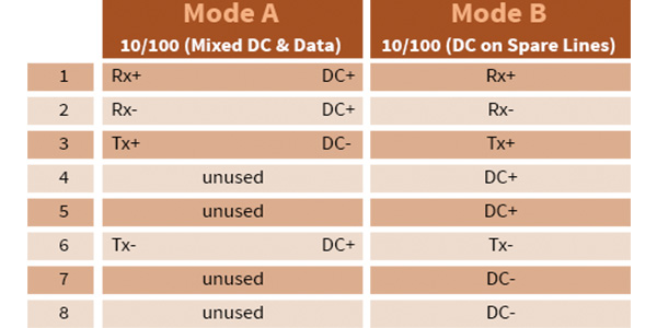
Mode A, sometimes referred to as Alternative A, uses two pairs of data pinouts 1-2 and 3-6 to transmit or receive power and data, and the other two pairs 4-5 and 7-8 pinouts are unused.
Mode B, also referred to as Alternative B, sends data using pinouts 1-2 and 3-6. Power is sent using data pin pairs 4-5 and 7-8.
What magnetic components are needed for PoE?
Magnetic components are used for various isolation, filtering, and power conversion functions in PoE equipment. For example, a high level of electrical isolation is required between devices attached to an Ethernet cable and any circuitry used to transmit or receive data over that cable. The basic Ethernet specification requires that equipment meet one of two electrical isolation tests:
- 1500Vrms at 50 Hz to 60Hz for 60 seconds, applied as specified by IEC 60950.
- 2250Vdc for 60 seconds, also applied as specified by IEC 60950.
While these two tests may seem at odds, they turn out to be compatible. The 1500Vms requirement corresponds to an equivalent of 2121 Vdc. Common practice is to design 2250Vdc isolation into PoE equipment, meeting both isolation tests.
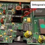
In the signal path, center-tapped 1:1 isolation transformers are used for injecting current, and common mode chokes are used to filter out EMI (figure 3). Signal path isolation transformers for both the transmit and receive sections are usually incorporated into a single package. Common mode chokes for both transmit and receive sections are also incorporated into a single package. In some cases, the isolation transformers and common mode chokes are all co-packaged.
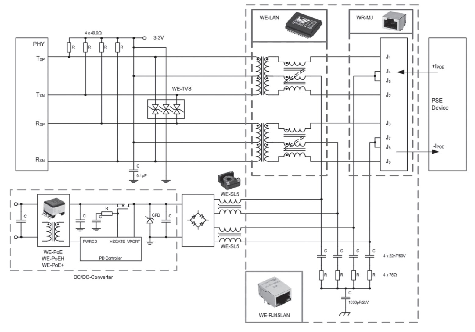
The dc/dc converter can be a source of common-mode interference in a PoE design. That usually requires using a common-mode choke designed to suppress as many broadband signals as possible from the switching frequency of the dc/dc converter without attenuating the PoE signal.
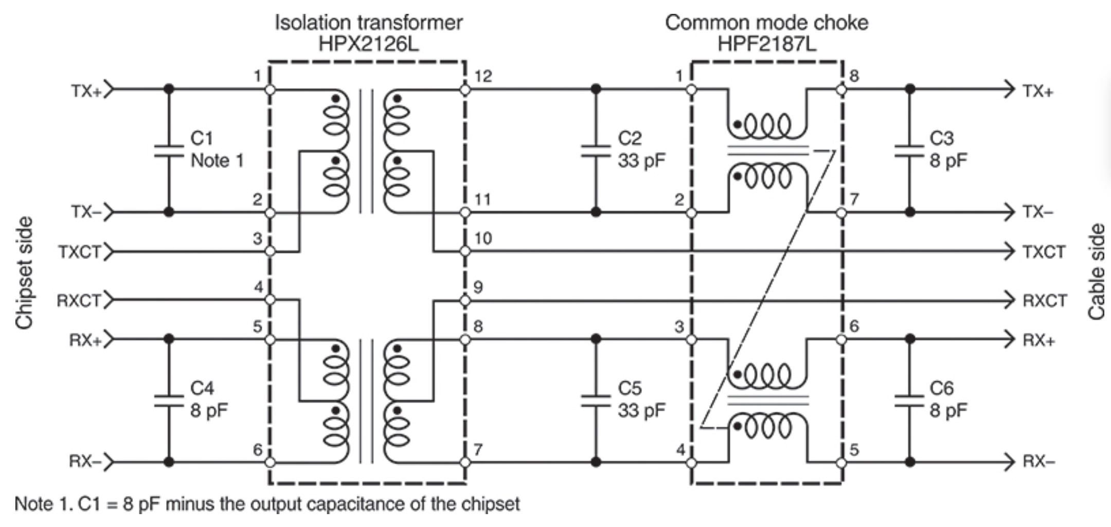
PoE applications place unique requirements on LAN transformers. Larger wire cross-sections are needed to handle the power, and the magnetic cores must be less susceptible to saturation in the presence of high PoE currents. In addition, PoE common-mode chokes are usually fabricated with trifillar or quadfillar windings, also to void saturation. Pairs of these magnetic components can support higher (double) power levels in higher Class PoE implementations. In some cases, PoE magnetics integrate signal path transformers, and common mode chokes into a single package for the most compact design (Figure 4).
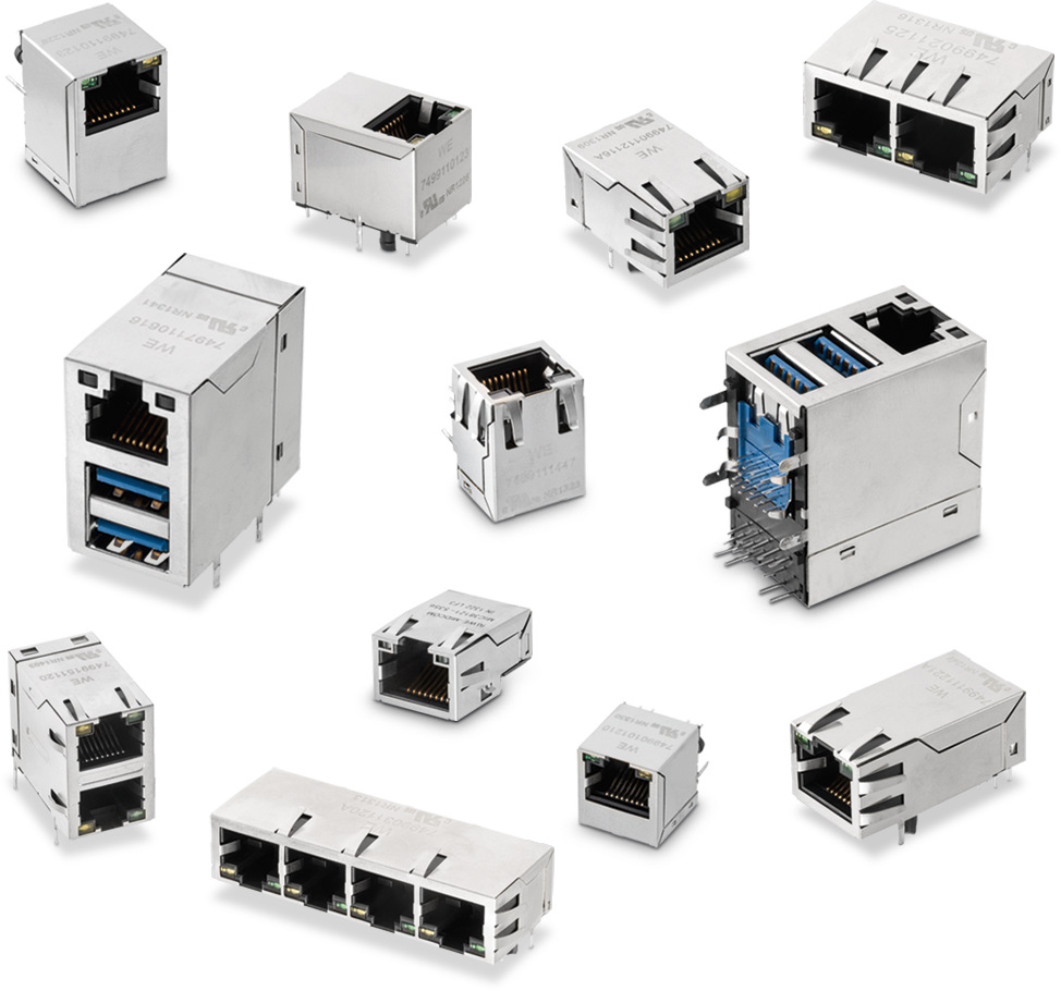
Ethernet jacks with integrated magnetics that support PoE can significantly simplify PCB design efforts and simplify peripheral powering in the total system while still meeting Ethernet data transmission requirements. RJ45 jacks (and assemblies of multiple RJ45s) with integrated transformers and common mode chokes are available in various configurations (Figure 5). Some are compatible with industrial Ethernet systems, such as EtherCAT or Profinet.
PoE power transformers are available that support flyback, forward and active clamp dc/dc converter topologies. Flybacks are better suited for higher voltage/lower current output designs and are more cost-effective, while more efficiency can be achieved with forward and active clamp topologies (Figure 6). Some PoE power transformers include support for synchronous rectification.
Typically, a flyback converter provides power to relatively simple PDs, such as a basic IP camera. At the same time, a forward topology may be needed to support more functionality, such as a tilt/pan/zoom IP camera. Both topologies can support the isolation requirements for PoE. Flyback converters provide the lowest-cost solution for PDs that consume under about 6A. With the proper magnetics, they can produce multiple output voltages. An advantage of a flyback dc/dc converter is that no output inductor is needed. Still, the higher output ripple current results in higher output capacitor cost and only moderate efficiency due to higher peak and RMS currents.
In contrast, the forward topology is the lowest-cost solution for PDs that consume over 6A of current. It is more costly than a flyback since it requires additional components, including an output energy storage inductor and an additional rectifying device (diode or synchronous MOSFET). In return for the greater cost and complexity, a forward converter has a low output ripple current. It uses a smaller capacitor, and this topology delivers higher efficiency because lower peak and RMS currents can utilize synchronous rectification.
The PoE transformer inside the dc/dc converter is isolated like the LAN transformer, typically 2,250Vdc primary to secondary side isolation; separating the SELF and TNV-1 circuits, as required by IEEE 802.3. PoE dc/dc converters tend to be compact devices and have switching frequencies of 200 to 300kHz, occasionally even higher. Some PoE transformers feature split primary and secondary windings to minimize leakage inductance.
Summary
PoE eliminates multiple ac/dc power supplies, reduces installation costs and improves installation flexibility, enables monitoring and controlling of PDs over the same network infrastructure used for data transfer. With PoE, PDs can be turned on or off or reset remotely. A variety of magnetic components are needed to provide electrical isolation, filtering, and power conversion functions in PoE equipment as specified in IEEE 802.3 to ensure that the primary mission of Ethernet to deliver high-speed and robust data connectivity is not compromised by the added function of power delivery.
References
Electrical isolation requirements in Power-over-Ethernet (PoE) power sourcing equipment (PSE), Applied Power Electronics Conference
Magnetics for Power over Ethernet, Coilcraft
The LAN-PoE Connection, Würth Elektronik
Understanding Ethernet Magnetics Features and Design Considerations, Abracon
What Is Power over Ethernet (PoE)?, Cisco