Advanced sensor simulation techniques can be used to validate functions for autonomous driving throughout the development process.
Caius Seiger, Dr. Gregor Sievers • dSPACE GmbH
Sensor-realistic simulation is a powerful way of validating sensor systems, which are an integral part of autonomous vehicles. Increasingly powerful computer systems make it possible to generate realistic sensor data in real time. This ability makes simulation efficient with several benefits for validating sensor control units.
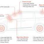
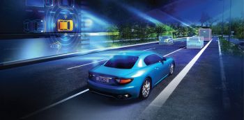
An important component for implementing autonomous driving according to SAE Level 5 involves capturing the vehicle environment via environment sensors. Manufacturers use different sensor types–such as cameras, radar, lidar, and ultrasonic sensors–for this purpose. Complex algorithms then merge the sensor data in high-performance processing units and use the results to make decisions.
Thus it’s crucial to validate the algorithms for fusion and perception, and those for the overall system. Various validation methods are available. Test drives make it possible to validate the entire autonomous vehicle, but they cover only a few critical situations and are relatively expensive.
An industry-proven method for the validation of driver assistance system algorithms is to play back recorded sensor data. For this method, a fleet of specially prepared vehicles is equipped with sensors. The vast volumes of data generated must be stored in powerful in-vehicle data logging systems and transferred to the cloud. The data is then evaluated, anonymized, tagged with terms for better retrieval, and labeled. The labeling is time-consuming and only partly automatable.
The recorded data is then stored in a way making it usable for testing during the development process and for release tests. One problem: This storage involves a great deal of time and effort and does not allow for changes in the sensor setup. If the next generation of vehicles is equipped with new sensors, they’ll require more test drives. Another drawback is that unforeseeable, rare events are difficult if not impossible to recreate.
Software-in-the-loop (SIL) and hardware-in-the-loop (HIL) simulation make it possible to test critical traffic scenarios. They can run through a nearly infinite combination of parameters including weather conditions, lens effects, and fault simulation for sensors.
Sensor-realistic simulation
Simulation has obvious advantages: It lets users configure all relevant components from the vehicle and sensor parameters to the driving maneuvers. And tricky traffic scenarios can be safely reproduced.
One of the main challenges of simulation is calculating the realistic sensor data in real time. For driver assistance systems, it is often sufficient to use sensor-independent object lists based on ground truth data (that is, data about the environment not from the vehicle sensors). The object lists are easy to extract from the traffic simulation. In contrast, autonomous vehicles process the raw data captured by a sensor front end in a central control unit. Calculation of the raw sensor data is much more time-consuming because it is based on the physical properties of each sensor. The raw data format is different for each sensor.
When inputting synthetic camera data, it is important to both create subjectively realistic images for the human user and to input the data at the right moment. The data must also be realistically generated for the sensor.
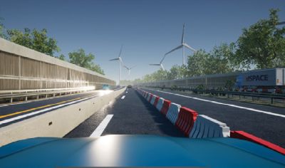
A graphics card is used to compute the raw data in real time because it can process more data in parallel than the main processor. This fact becomes clear from a closer look at radar and lidar sensors, because their metrological computation requires complex ray tracing. For example, suppose radar sensor waves reflect back to the sensor via the guard rail and from another object. Here, the radar detects a ghost target and adds it to the detection list, though the object does not exist. These types of operations are complex but can easily be parallelized so the calculated sensor data can be input into the ECU in real time.
HIL test for sensor fusion controllers
HIL test benches make it possible to test real ECUs in the lab by stimulating them with recorded or synthetic data. Consider an example setup for open- and closed-loop HIL simulation as well as raw data input for a front camera. Here, the camera image sensor, including the lens, is replaced and simulated by the HIL environment.
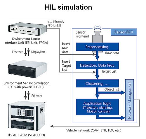
The dSPACE traffic and vehicle dynamics simulation is executed on a real-time PC with an update interval of 1 msec. In addition, the real-time PC for the restbus simulation (Restbus simulation is a technique used to validate ECU functions by simulating parts of an in-vehicle bus such as the controller area network.) is connected to the vehicle network (CAN, Ethernet, FlexRay, etc.).
The results of the vehicle simulation are transferred to a powerful computer. The computer then generates a three-dimensional representation of the environment. The relevant, parameterized sensor models are calculated on the basis of this representation. Simulation and testing providers, such as dSPACE, can furnish these sensor models.
As an alternative, users can integrate sensor models from Tier 1 suppliers via the open simulation interface (OSI) which also protects supplier intellectual property. Furthermore, dSPACE supports standards such as OpenDrive for defining streets and OpenScenario as a format for defining scenarios.
The raw sensor data is transferred to the dSPACE Environment Sensor Interface Unit (ESI Unit) via the DisplayPort interface of the GPU. This FPGA-based platform executes all remaining parts of the sensor models. For example, it executes light control or simulates the I2C interface of the image sensor.
So far, no supplier-independent interface standard has been established for transferring raw sensor data. So a test system for raw sensor data injection must support a wide range of sensor interfaces. The ESI Unit is highly modular and supports all relevant automotive sensor interfaces. Automotive cameras typically use TI FPD-Link III and IV, Maxim GMSL1 and GMSL2, and MIPI CSI-2 with more than 8 Gbit/sec. Most radar and lidar sensors have an automotive Ethernet interface with up to 10 Gbit/sec. However, the interfaces used for cameras are also increasingly used for radar and lidar.
The HIL simulation of autonomous vehicles with dozens of sensors presents a particular challenge. It takes a great deal of processing power (CPU, GPU, FPGA) to realistically simulate all the sensors. In addition, the sensor and bus data must be synchronized depending on the vehicle and sensor architecture.
In the case of (rest)bus data, a real-time operating system, such as dSpace SCALEXIO, performs these tasks across multiple computation nodes. The sensor simulation at the raw data level requires both GPUs and FPGAs and thus calls for new synchronization concepts. Furthermore, all components of the simulator setup must be optimized for low end-to-end latencies so the control algorithms of the ECU can be tested.
All in all, sensor simulation is a powerful, integrated, and uniform way of validating autonomous vehicles. The dSPACE solution described here ensures a high level of productivity in the validation of sensor-based ECUs at all stages of the development and test process.