The electronic TENS (transcutaneous electrical nerve stimulation) therapy pain relief kit called Dr. Pocket uses electronic pulse stimulation via TENS to deliver
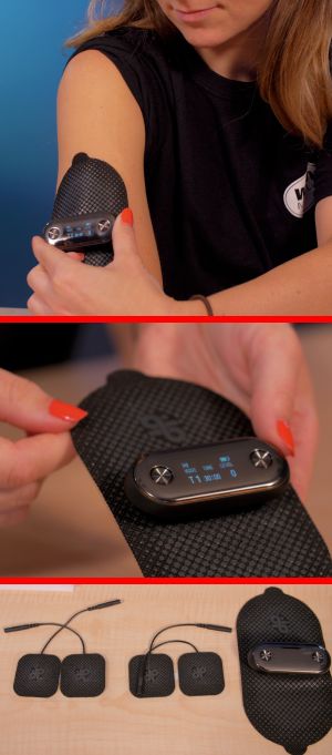
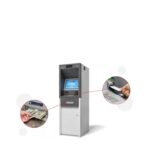
Top, Mr. Pocket in use with the large flexible electrode pad. Center, a view of the read-outs on the Mr. Pocket display screen. Bottom, the unit also comes with four small electrode pads.
electric impulses through electrodes in a pad that sits on the user’s skin. This device has multiple modes of different pulse frequencies covering transcutaneous electrical nerve stimulation and powered muscle stimulation which are said to mimic the action potential coming from the central nervous system to trigger muscle contractions.
We tried Dr. Pocket in its various modes and intensities. Users have their choice of eight modes: circulation, kneading, beating, scraping, cupping, relaxing, E1 and E2. And users can customize a session to have different modes kick in at different times and at different intensities. The output consists of 100-µsec pulses coming at rates of 1.2, 20, 62.5, 100, and 160 Hz depending on the mode, and a swept-frequency mode spanning 12.5 to 55.5 Hz.
There is a display built-into the super small (about 3×1.1-in) electronics module. The Dr. Pocket TENS kit works via a smartphone app, as do several other TENS devices. The crisp display in the electronics module augments the information available via app, giving readouts of operation mode, time remaining, and stimulation level when the device is operating. It also shows the level of charge when the device is hooked to the charger.
There are other TENS devices on the market, but Dr. Pocket has several features that distinguish it from its competitors. TENS devices work via a pad that touches the skin and contains the electrodes that actually do the stimulation. The usual way of connecting the TENS electronics to the pad is through mechanical snaps. But Dr. Pocket eliminates the snaps in favor of magnetic connections – the user merely places the TENS electronic module’s connection terminals near the pad terminals and magnets do the rest. Ditto for the connections to the charger.
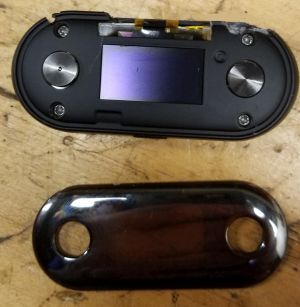
The Mr. Pocket electronics module (top) with the translucent cover off (bottom) gives a good view of the flat display and the four screws holding the case together.
The electronics module disassembly starts by taking off the translucent cover that sits overtop the display readout. The cover pops off to reveal four small Philips screws holding the case together. Thankfully, these screws are not so small that they demand a special screwdriver.
But removing the top of the case reveals the circuit board which is indeed attached to the case with super-small Philips screws. We had the correct screwdrivers on hand from previous teardown efforts, so we were in business. The display readout sits on the other side of the PCB and is held against the case by the 3.7-V lithium-ion battery. This side of the PCB also contains the two pushbutton controls and the side-mounted mechanical on/off switch.
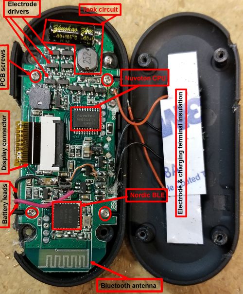
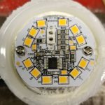
The PCB. The fact that this is a preproduction unit is made clear by the battery leads soldered to board components rather than to the PCB and an insulator for the charging and electrode terminals that is obviously positioned by hand.
Virtually all of the rest of the components sit on the other side of the PCB. Two ICs run the whole show. One is an nRF51822 SoC Bluetooth Low Energy device from Nordic Semiconductor. This chip contains an ARM Cortex-MO CPU with up to 256 KB of flash and up to 32 kB of RAM.
We should note that we got an early version of Dr. Pocket. That would account for a couple of fabrication techniques we noted that are common to prototypes. Most notable of these is that the battery leads are soldered directly to component leads rather than onto PCB solder pads. One of these devices is a five-pin chip which contains markings that are ambiguous but which we surmise probably handles the battery charging. Also on the PCB is a soldered jumper lead that we suspect will disappear when the TENS device reaches volume production.
The brains of the device is an N76E003 chip from Nuvoton in Taiwan. This chip basically mimics the instruction set and architecture of the old 8051 processor originally from Motorola. One particular aspect of the 8051 architecture worth noting is the built-in six-channel pulse-width modulation output. This would seem to come in handy for developing the various square wave signals necessary for driving the electrode pads.
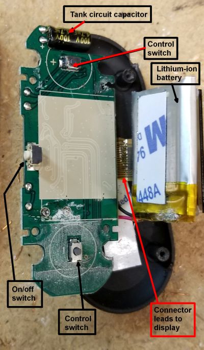
The PCB reverse side holds the actuator switches, the on/off switch located on the side of the case, and provides a spot for the lithium-ion battery. The flat display sits on top of the battery. The battery does double duty, acting as a platform that holds the flat display flush against the case.
The section of the device devoted to driving the electrodes seems to include ten discrete transistors and a tank circuit consisting of a 4.7 µF capacitor and what is either a 2.5 µH or 2.5 mH coil. (The markings for the two inductor values are the same. The multiplier depends on the coil manufacturer.) This implies a resonant frequency of either 464.3 or 146.8 Hz respectively.
It should also be noted that the PWM output of the Nuvoton chip is optimized for driving electric motors. The six channels are there for handling three-phase electric motors. It’s possible the TENS unit uses all six channels or a subset of them in parallel to get a higher output for the excitation modes that require a higher output.
Principle of operation
We can glean some of the functions of the Dr. Pocket drive electronics from patents filed by Neurometrix, a noted developer of an earlier TENS device called the Quell. It’s likely the basic operation of the Quell resembles that used in Dr. Pocket.
As the Neurometrix patent explains, the Quell uses a current source, rather than a voltage source, to drive the electrodes, because stimulation current is independent of the impedance between the electrode and the skin, which changes while the device is in use. The voltage, of course, will change if the impedance changes. Thus it’s likely the 1byone TENS device also synthesizes a current source to drive the electrode pad.
The Quell, however, drives the electrodes with a single n-channel power MOSFET typically used in ac/dc power supplies. So its electrode drive is completely different than that employed by Dr. Pocket.
Another difference between the Quell and the Dr. Pocket TENS is the presence of accelerometer on the Quell. It’s there because the Quell is designed so its user can walk around wearing it, and walking around can induce mechanical shocks that can cause momentary changes in how much of the electrode touches the skin. These momentary interruptions, in turn, change the electrode impedance enough to shut off the device.
The Dr. Pocket TENS unit, on the other hand, isn’t designed to be worn by someone who is wandering around and bumping into things. So its designers decided it doesn’t need an accelerometer onboard to warn that such things are happening.
All in all, the Mr. Pocket TENS device is an interesting piece of electronics that delivers transcutaneous stimulation at what seems to be a budget price.


I am developing medical devices that attach to the body in a similar fashion.
I am taking a LOT of effort to make it impossible to have the device, or any of its leads, in contact with the body, and also have the charger connected at the same time.
There are just so many poorly made chargers out there, and if the insulation breaks down, then the patient could be electrocuted.
Might only be once in many millions …. but a nasty hi $$$$ result if it can happen.
Cannot tell if this device follows these guidelines.
The Dr. Pocket electronics can’t be charged while connected to the pads that actually do the work on the body. When it’s connected to the pads, the charging connections are blocked by the pads. Similarly, when it is charging, the pad electrodes are blocked by the charging connections.
Thanks for the tear down!
Resonant frequency for the tank would be:
f = 1/2pi.rt(LC) = 1.47kHz (2.5mH) or 46.4kHz (2.5uH).
If the tank makes a single resonant pulse it would be a half cycle, ie. 340us or 11us.
It would be interesting if you connected a 500R load to the electrodes and check it with a scope.