Engineers are often tasked with making sense of what initially looks like a tangle or wires, electrical energy sources, and components. Before attacking such situations with scope probes, it’s good to recall a few basics.
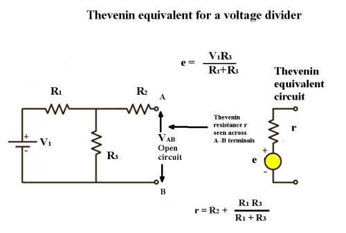
Thévenin’s Theorem states it is possible to simplify any linear circuit to a single equivalent circuit composed of a single voltage source and series resistance connected to a load. The theorem is valid only when the circuit that is to be simplified is linear, i.e. none of the constituent circuit elements are exponents or roots. To comply with this requirement, we are in safe territory provided all components are passive – resistors, capacitors and inductors. Any semiconductor switches would render Thévenin’s Theorem invalid. Depending on polarities, diodes might be treated as either open circuits or small resistors for purposes of first-cut analysis. (The same restriction applies to the Superposition Theorem).
In power systems where the load resistance is subject to change, calculation of the equivalent circuit would need to be recalculated multiple times. Here Thévenin’s Theorem is extremely useful. It lets the individual performing the analysis provisionally disregard the changing load resistance and create a working template enabling the simplification process to proceed.
To perform the transformation correctly, all ideal voltage sources in the circuit are replaced by short circuits, and all ideal current circuits are replaced by open circuits. Also recall that in performing the Thévenin operation, all voltage and current sources are replaced by their internal resistances. For an ideal voltage source, we substitute a short circuit and for an ideal current source, an open circuit. This is counterintuitive until you consider that replacement of the voltage and current sources do the exact opposite of what the original sources accomplish. In a voltage source, a difference of electric potential is created. In the equivalent circuit, the short circuit equalizes potential. Similarly, a current source has the effect of generating a flow of current, which an open circuit interrupts.
As originally formulated, Thévenin’s Theorem was envisioned to apply to dc circuits. But it turned out it worked in ac circuits as well provided that resistances were generalized to denote the broader meaning of impedances.
The question now arises: How do we determine the Thévenin equivalent resistance and voltage for a chaotic assembly of devices, voltage and current sources that need to be rationalized? If VTh is the equivalent circuit’s open-circuit voltage, then it is also the open-circuit voltage of the original circuit. Accordingly,
RTh = V/I, and
VTh = R x I
Norton’s Theorem is closely related to Thévenin’s Theorem. Norton’s Theorem likewise applies only to linear circuits. It says that any linear circuit containing multiple electrical sources can be replaced by a single constant-current source in parallel with one resistor.
 As in the Thévenin Circuit Theorem, the object of the exercise is to find the equivalent circuit. To do so, we first remove the load, either a resistor or similar passive component. Then, short-circuit the voltage sources or open-circuit the current sources. Short-out the output terminals and calculate or measure the current flowing through the load.
Another interesting aspect in the discussion of the Thévenin and Norton equivalents is the notion of maximum power transfer in electrical circuits. Resistance (impedance in ac systems) is ordinarily thought to be an attribute of the load in an electrical circuit. However, it is also true that resistance or impedance is present as a measurable quantity in a source. In a generator, for example, it is in part a consequence of the dc resistance in the electrical windings. This internal resistance is equivalent to a hypothetical series resistance that would be located outside of the generator housing.
It can be determined by observation that maximum power transfer between the source and load takes place when their impedances are equal. It is the task of the designer to match these impedances most of the time, except when attenuation is desired. This phenomenon can be observed, especially in data transmission, when there is an impedance mismatch. What happens is kind of strange. The transmission begins at the source as an impulse moves at substantially the speed of light in the direction of the load. When the impedances at the two ends of the transmission line are not equal, data bits are not absorbed at the load but instead reflect back toward the source. These waves or information (depending on how you look at it) then travel in the reverse direction and collide with waves traveling in the opposite direction. The resulting interference causes data corruption and loss.
The other way to describe the situation is algebraically. As always, Ohm’s law applies. As the impedance at the source lessens, the voltage rises as does the current. As the impedance at the load lessens, voltage and current drop. When impedances at both ends are equal, power transfer is maximized.
There are other important electronics theorems. Here’s a partial rundown:
Kirchhoff’s Circuit Laws, formulated by Gustav Kirchhoff (1824-1887), includes the first law, which states that the algebraic sum of currents in a network of conductors that join at a single node is zero. The second law states that in a closed circuit, the directed sum of the voltages is zero. The first (current) law is basic to all electrical troubleshooting because it implies that in a non-bifurcating circuit the current is everywhere the same, including within the source and within the load.
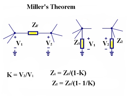
The Miller Theorem says a floating impedance can be converted to two grounded impedances through these relationships.
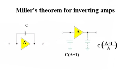
Another aspect of Miller’s Theorem is that the capacitance between the input and output of an inverting amplifier is equivalent to separate input and output capacitances to ground.
The Miller Theorem is closely related to Kirchhoff’s Circuit Laws. It states that a floating impedance, energized by two series-connected voltage supplies, may be conceptualized as two grounded elements with corresponding impedances. The theorem is applicable in many electronic design projects including feedback amplifiers, resistive and time dependent converters, negative impedance converters and high-frequency transistor amplifiers.
Millman’s Theorem, formulated by Jacob Millman (1911-1991), is another body of knowledge closely related to Kirchhoff’s Circuit Laws. It lays out a method for calculating the voltage at the outputs of a circuit composed of parallel branches. When the number of voltage sources is too high to permit solution by means of series and parallel reduction, Millman’s theorem simplifies the solution, because simultaneous equations are not required. It cannot, however, be used for circuits that do not conform to a limited pattern, such as unbalanced bridge circuits.
The Belevitch Theorem, formulated by Vitold Belevitch (1921-1999), provides methodology using complex matrix theory for determining whether a circuit is lossless. In this context, lossless means that the network contains lossless components only, i.e. ideal inductors and capacitors, with no resistors. It must be remembered that reactive components have impedance but they are nevertheless lossless. An inductor, for example, impedes current flow as it comes on line, expending electrical energy to establish a magnetic field. But during the time that the waveform of applied voltage is diminishing in amplitude, the magnetic field collapses, returning energy to the circuit so that there is no overall loss.
These various network analysis protocols are applicable in separate areas, and it is only by being able to deploy each of them as needed that engineers can rationalize the complexities that arise in individual situations.

Leave a Reply
You must be logged in to post a comment.