Compared with one-switch topologies, two- and four-switch power conversion topologies have several benefits in addition to the ability to process higher power levels. This FAQ will review some of the basic two-, and four-switch topologies. It will look at where they are used and their performance tradeoffs. This article does not consider various switched capacitor topologies; a review of those approaches can be found in “Switched capacitor power conversion for electronic systems.” For a review of one-switch topologies, see the previous FAQ in this series, “One-switch power conversion.”
Two Switch Flyback Converter
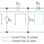
Compared with a one-switch flyback, the second switch is added on the transformer’s high side, resulting in the voltage stress on each switch clamped to the input voltage (Figure 1). Both switches are turned on and off simultaneously. The flyback “transformer” operates as a two-winding coupled inductor, and the leakage inductance can destroy the switch in a one-switch flyback if not managed. The clamp diodes in the two-switch topology recycle the leakage energy back to the input and clamp the turn-off voltage across each switch to the input voltage. The need for an RCD clamp found in one-switch flybacks is also eliminated since the leakage inductance energy is clamped and recycled back to the input, improving efficiency.
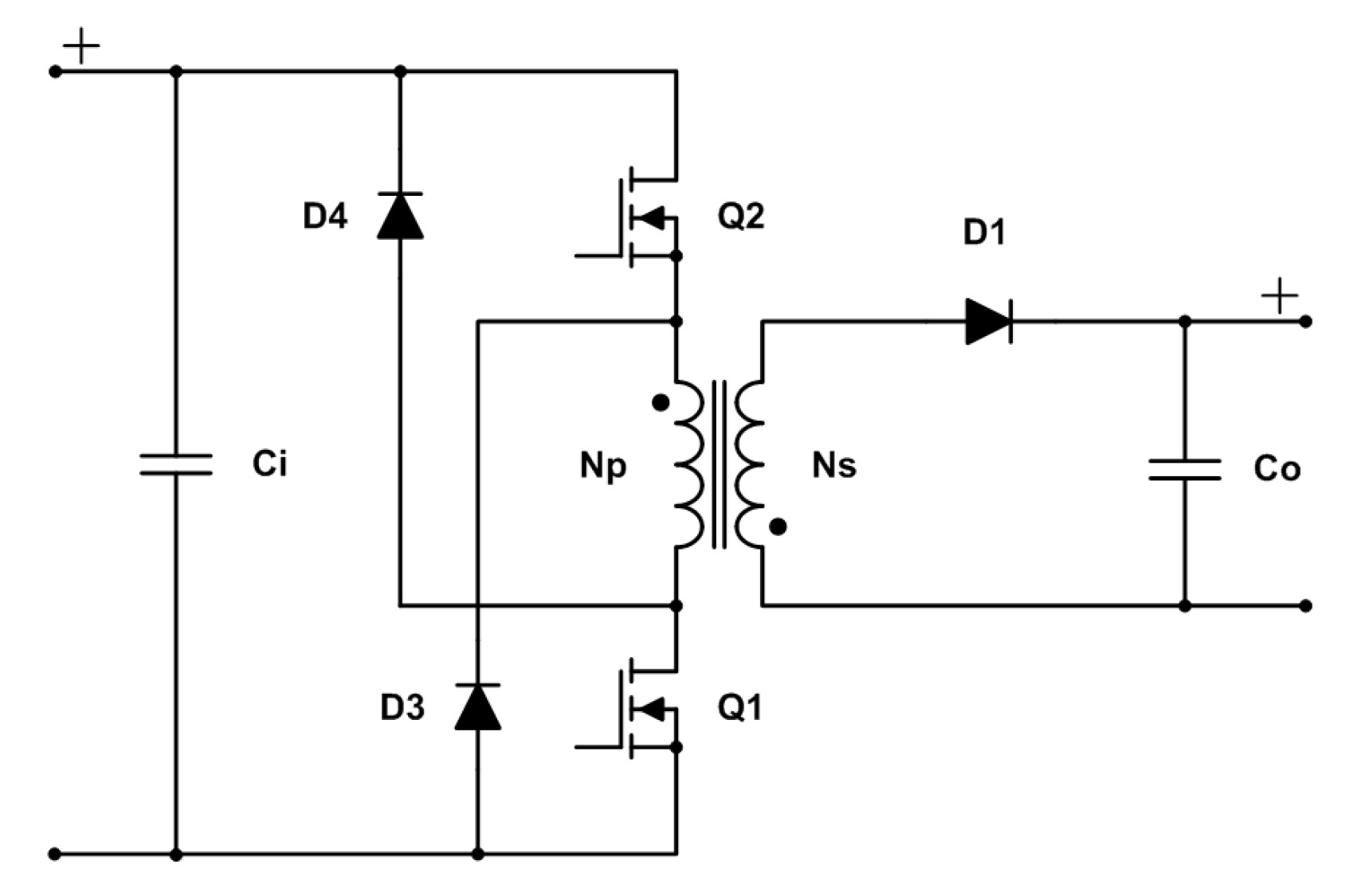
The operation of this topology is particularly useful in auxiliary power supplies powered by a three-phase input rail and other high-voltage designs. The two-switch design caps the maximum voltage stress on the switches and eliminates clamping losses, reducing thermal stress and boosting efficiency.
Two Switch Forward Converter
As in the two-switch flyback, the second switch in a two-switch forward converter serves to clamp the voltage on each switch at the input voltage, reducing stresses, and the switches are simultaneously turned on and off. When the switches are off, diodes conduct all the magnetizing energy in the primary along with any energy stored in leakage inductances back to the input. To ensure transformer reset, the on-time of the switches is less than 50%. Two-switch forward converters can operate over a wide range of input voltages and provide multiple isolated outputs. They have relatively less electromagnetic interference (EMI) and limited operating frequency. Compared with a one-switch forward topology limited to about 150W, a two-switch design can support loads of several hundred watts.
Push-Pull Converter
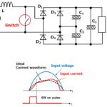
Compared with two-switch flyback and forward topologies, where both switches are turned on and off simultaneously, the transistors are alternatively turned on and off in a two-switch push-pull topology (Figure 2). Current is drawn from the input during both halves of the switching cycle. Push-pull converters have steadier input current, create less EMI on the input line, and are more efficient in higher power applications. Those benefits come at the cost of higher complexity. If the input voltage is relatively stable, some applications can benefit from using an unregulated push-pull converter.

Small differences in the characteristics of the switches can result in unbalance in the transformer flux. The unbalance is cumulative since the transformer is not completely reset to zero at the end of each switching cycle. If left uncorrected, this so-called “flux walking” can result in transformer saturation and the destruction of one or both switches. Cycle-by-cycle current sensing and current limiting need to be included in the control circuitry to correct for flux walking.
Unregulated Push-Pull
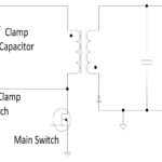
The push-pull topology is also widely used in unregulated isolated converters. If the input voltage is stable, the transformer turns ratio determines the output voltage, which can be higher, lower, inverted, or bipolar. An unregulated push-pull converter can be designed as a transformer-coupled free oscillator (Royer topology) that operates with a 50% duty ratio and its most efficient operating point (Figure 3).
Without the need for any feedback components or a controller, unregulated push-pull converters can be constructed with about ten components, resulting in a small solution size. However, these converters require a minimum load of at least 10% to keep the output voltage within a safe level. If loads under 10% are anticipated, a dummy load resistor or a Zener diode clamp should be added. For loads above 10%, load regulation of this design is typically ±2%. When applicable, unregulated push-pull converters can be one-third less expensive than a regulated topology.
The complex transformer design, six windings compared with four windings in a regulated push-pull, is a disadvantage of the unregulated topology. In addition, there is no simple way to stop the free-running oscillator, making over-temperature, over-current, and short-circuit protection challenging to implement. They are usually absent in these designs.
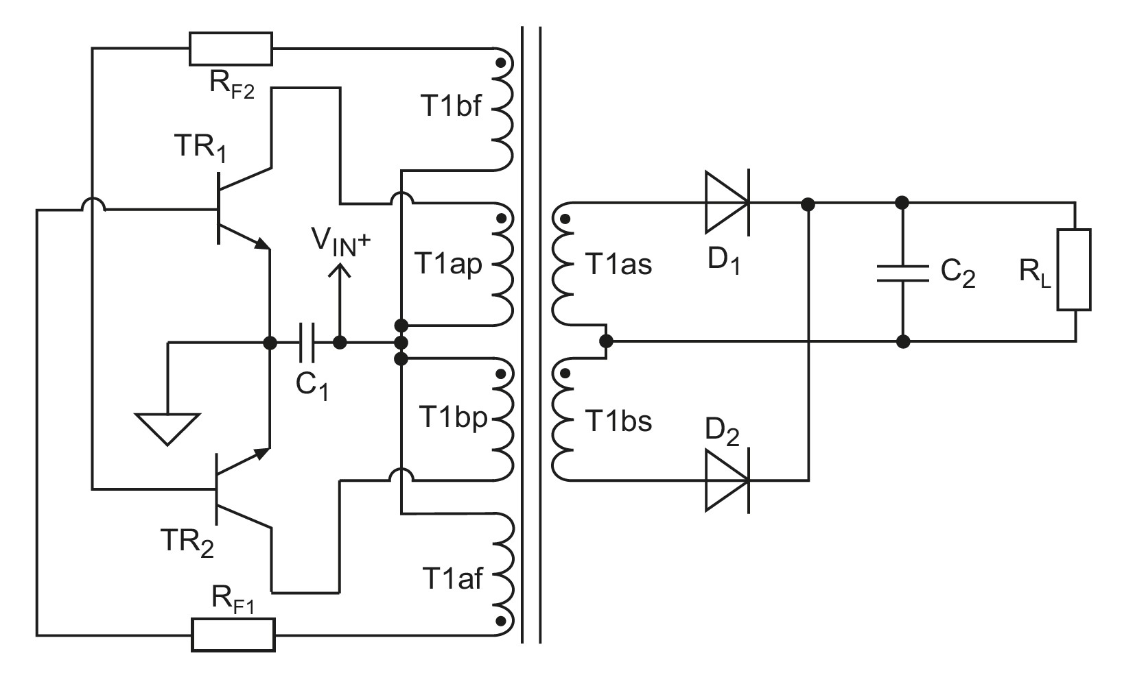
Weinberg Converter
Take a push-pull topology and add a flyback-current-fed front end, and the result is a Weinberg topology (Figure 4). The addition of the coupled inductor on the input eliminates the problem of overlap switching and flux walking—the coupled inductor results in continuous output current, which reduces the output filter capacitors requirement.
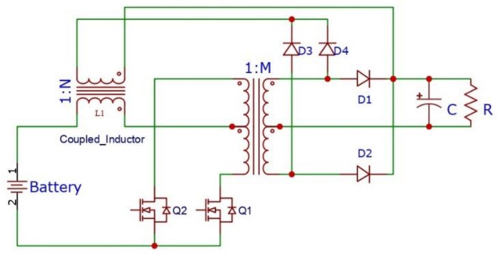
One application for Weinberg converters is battery discharge regulators (BDRs) in spacecraft. A BDR is used to keep the battery bus voltage within specified limits and improve the battery’s life. Weinberg converters are fault-tolerant, robust, and reliable, making them suitable for use in space-borne applications. The use of coupled inductors, and the continuous output current that reduces output filter requirements, contribute to the small size and low weight of these converters.
Half-Bridge Converter
A half-bridge converter is more complex than a flyback or forward topology but can deliver more power and use smaller, less expensive components. The primary side capacitors produce a constant voltage of half Vin across the primary winding (Figure 5). The switches alternate on and off, switching the voltage (0.5 Vin) across the primary winding. The lower voltage rating of the switches enables lower-cost devices. The positive and negative voltage swings on the primary require a full-wave rectifier for the output. This is another advantage since half-bridge converters fully utilize the core flux and the secondary winding.
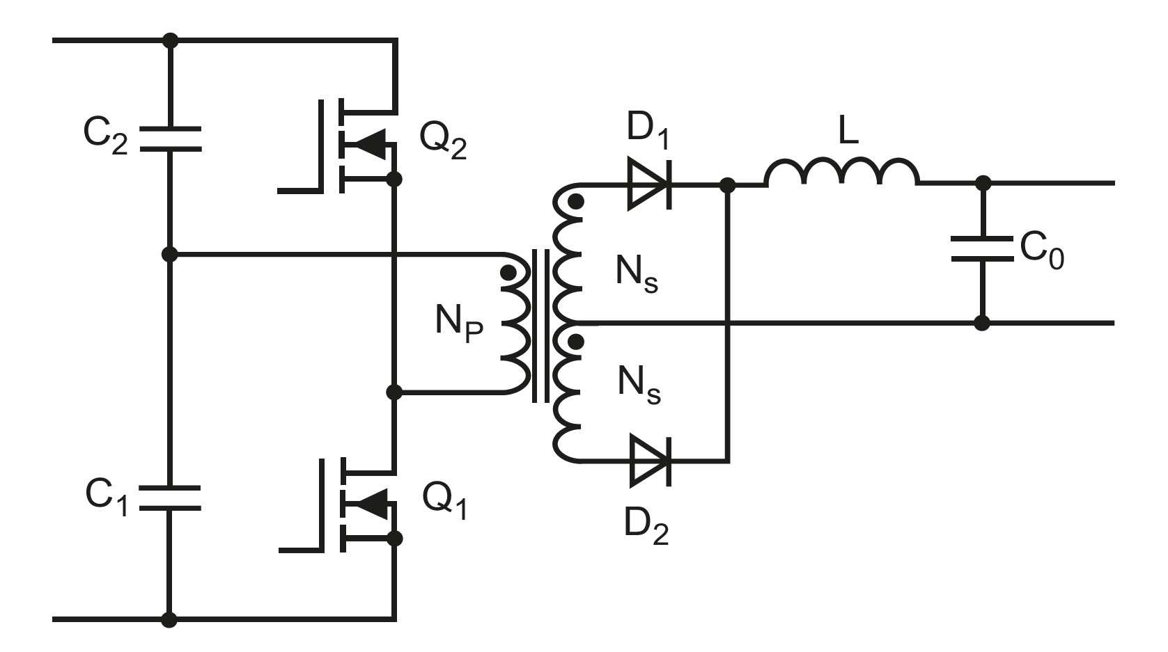
Since the secondary side of the transformer operates at the double the basic switching frequency, smaller and lower-cost filter components can be used. Overall, half-bridge circuits produce more compact power converters compared with some other topologies.
Four switch topologies
Full-Bridge Converter
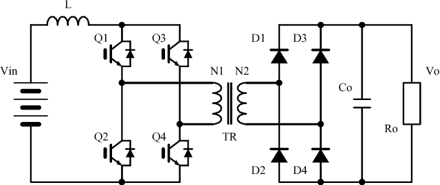
A full-bridge topology consists of four switching devices (Figure 6). Each pair of switches turns on for half of the cycle, with the two pairs alternative and symmetrically driving the transformer. Q1 and Q4 conduct in the first switching period, and the other pair of transistors Q2 and Q3 conduct during the next one. The transformer provides isolation in addition to voltage transformation. Compared with a half-bridge that requires a center-tapped secondary, the transformer in a full bridge is simpler in construction with no center tap needed.
Both the half- and full-bridge topologies are flexible and can produce dense power converters. They are used in various applications, including ac/dc power supplies, dc/dc converters, and dc motor drives. Sophisticated control schemes that support bidirectional power flow can be found in electric vehicles and various industrial applications.
Phase-Shifted Full-Bridge Converter
A phase-shifted full-bridge (PSFB) operates similarly to a conventional full-bridge. Instead of hard switching, the full-bridge converter clamps and recycles the energy stored in the power transformer’s leakage inductance to softly turn on each of the four switches. Zero voltage switching turns the power switches on and off when their drain-to-source voltage is at zero volts, eliminating the instantaneous turn-on power loss caused by the drain-to-source capacitance (COSS) and the parasitic capacitance discharge. This reduces switching-related EMI, the need for primary side snubbers, and also increases efficiency. PSFBs are compact and efficient power converters and are found in various applications such as telecom power systems, server power supplies, battery charging systems, and renewable energy installations.
Summary
Two- and four-switch power conversion topologies provide the efficient operation and isolation needed in a wide variety of computing, communications, industrial, and other applications. Depending on the control strategy employed, these converters, especially bridge topologies, can support bidirectional power conversion in electric and hybrid vehicles and battery-powered systems. Multiple power switches also reduce the voltage stress on individual switches, improving robustness.
References
Basic Concepts of Linear Regulator and Switching Mode Power Supplies, Analog Devices
DC/DC Book of Knowledge, RECOM Power
Isolated and wide input ranged boost full bridge DC-DC converter with low loss active snubber, IEEE
Power Topologies Handbook, Texas Instruments
Practical Battery Discharge Regulator with Weinberg Topology, International Journal of Recent Technology and Engineering
Switched-mode power supply, Wikipedia