• Skip to primary navigation
  • Skip to main content
  • Skip to primary sidebar
  • Skip to footer

Electrical Engineering News and Products

Electronics Engineering Resources, Articles, Forums, Tear Down Videos and Technical Electronics How-To's

  • Products / Components
    • Analog ICs
    • Battery Power
    • Connectors
    • Microcontrollers
    • Power Electronics
    • Sensors
    • Test and Measurement
    • Wire / Cable
  • Applications
    • 5G
    • Automotive/Transportation
    • EV Engineering
    • Industrial
    • IoT
    • Medical
    • Telecommunications
    • Wearables
    • Wireless
  • Learn
    • eBooks / Handbooks
    • EE Training Days
    • Tutorials
    • Learning Center
    • Tech Toolboxes
    • Webinars & Digital Events
  • Resources
    • White Papers
    • Educational Assets
    • Design Guide Library
    • Digital Issues
    • Engineering Diversity & Inclusion
    • LEAP Awards
    • Podcasts
    • DesignFast
  • Videos
    • EE Videos and Interviews
    • Teardown Videos
  • EE Forums
    • EDABoard.com
    • Electro-Tech-Online.com
  • Bill’s Blogs
  • Advertise
  • Subscribe

What is inrush current?

May 26, 2017 By Janet Heath

Inrush (in-rush) current is a sudden large flow of current that exceeds the usual, steady-state operating current, and can be a problem for any circuit. Inrush is most often associated with turning on equipment. Inrush current can be caused by large-capacity decoupling capacitors that draw a lot of current as they initially get charged up. Another application that invites inrush current is equipment that draws more energy until it heats up, perhaps using components that build in resistance only as the local operating temperature increases, leaving the equipment vulnerable to inrush peak currents upon initial startup.

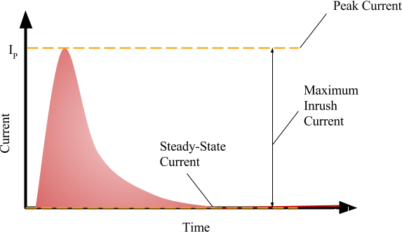
Inrush current reaches a peak current in this diagram then quickly decays to a steady-state (undershoot not shown). Components must be able to withstand a brief moment at peak current. (Image credit: KC Reese, III).

Inrush current is short-lived; the current draw will begin to settle into a steady-state condition but this is no consolation if components get fried at startup.

Why should you care about inrush current?

In-rush current is sometimes overlooked. Inrush is often the maximum peak value of current that is actually experienced, and the tolerance of components that are in the path of inrush current should be considered. If inrush isn’t accounted for, a breaker can trip every time a piece of equipment is turned on. Adjusting the tolerance of the breaker slightly may help, as long as components can withstand the peak values at in-rush.

The duration of the peak current experienced at in-rush is also a factor. Some components can withstand brief periods of maximum current, a specification which might be found in component data sheets. Components can get very hot if there’s too large a current draw for too long, and permanent damage can occur. But you don’t have to be concerned about maximum possible inrush if you simply protect components, headers/connectors, and traces on your printed circuit board (PCB). If the current flow is choked down during initial startup, then you have little to worry about.

What can I do to protect a PCB from inrush current?

You can limit the amount of current using circuit protection devices. A passive device like a thermistor will limit current as a function of temperature. The thermistor’s resistance is at its highest when the temperature of the thermistor is at its lowest. As an example, if a power supply is turned on, it experiences a more limited amount of current if a thermistor is choking down on the maximum amount current in the inrush current path. As the thermistor operates, it heats up and resistance begins to decrease in value. This works if the thermistor is not already hot. If the capacitors discharge faster than the power supply (or thermistor) cools down, then inrush may not be adequately limited by the thermistor in every use case.

Active devices are more expensive than thermistors but work to actively switch current to bypass components at inrush. Active device options include circuits that switch incoming current away from sensitive components in what is sometimes called a “soft start,” as well as voltage regulators, DC/DC converters or low drop out (LDO) voltage regulators with built-in soft start features. Circuits that switch current away from the circuit you’re trying to protect can be discrete or integrated and may use thyristors, triode AC switches (Triacs), MOSFETs or other devices. Various integrated solutions such as load switches (e.g., Texas Instruments’ TPS229xx) can also provide the needed protection.

Factors that influence choices in circuit protection will include size, additional component cost, and power consumption. You will have to evaluate the trade-offs of a circuit protection scheme against possible use cases, product quality, reliability, and perhaps company reputation.


The post What is inrush current? appeared first on Power Electronic Tips.

You Might Also Like

Filed Under: FAQ, Featured, Power Electronic Tips Tagged With: basics, FAQ

Primary Sidebar

EE Engineering Training Days

engineering

Featured Contributions

zonal architecture

Addressing zonal architecture challenges in the automotive industry

zonal architecture

Addressing zonal architecture challenges in the automotive industry

A2L refrigerants drive thermal drift concerns in HVAC systems

Why outdoor charging demands specialized battery connectors

How Li-ion batteries are powering the shift in off-highway equipment

More Featured Contributions

EE Tech Toolbox

“ee
Tech Toolbox: 5G Technology
This Tech Toolbox covers the basics of 5G technology plus a story about how engineers designed and built a prototype DSL router mostly from old cellphone parts. Download this first 5G/wired/wireless communications Tech Toolbox to learn more!

EE Learning Center

EE Learning Center
“ee
EXPAND YOUR KNOWLEDGE AND STAY CONNECTED
Get the latest info on technologies, tools and strategies for EE professionals.
“bills
contribute

R&D World Podcasts

R&D 100 Episode 10
See More >

Sponsored Content

Designing for Serviceability: The Role of Interconnects in HVAC Maintenance

From Control Boards to Comfort: How Signal Integrity Drives HVAC Innovation

Built to Withstand: Sealing and Thermal Protection in HVAC Sub-Systems

Revolutionizing Manufacturing with Smart Factories

Smarter HVAC Starts at the Sub-System Level

Empowering aerospace E/E design and innovation through Siemens Xcelerator and Capital in the Cloud

More Sponsored Content >>

RSS Current EDABoard.com discussions

  • Sendust vs Ferrite for SMPS
  • connector model question
  • Shoot through current in LLC & PSFB
  • sim7090g
  • MIC2309 I-LIM Pin Voltage/Current for Resistor Wattage Selection

RSS Current Electro-Tech-Online.com Discussions

  • More fun with ws2812 this time XC8 and CLC
  • the point I don't understand about signal systems
  • I Wanna build a robot
  • Epson crystal oscillators
  • Impact of Tariffs on PCB Fab
Search Millions of Parts from Thousands of Suppliers.

Search Now!
design fast globle

Footer

EE World Online

EE WORLD ONLINE NETWORK

  • 5G Technology World
  • Analog IC Tips
  • Battery Power Tips
  • Connector Tips
  • DesignFast
  • EDABoard Forums
  • Electro-Tech-Online Forums
  • Engineer's Garage
  • EV Engineering
  • Microcontroller Tips
  • Power Electronic Tips
  • Sensor Tips
  • Test and Measurement Tips

EE WORLD ONLINE

  • Subscribe to our newsletter
  • Teardown Videos
  • Advertise with us
  • Contact us
  • About Us

Copyright © 2025 · WTWH Media LLC and its licensors. All rights reserved.
The material on this site may not be reproduced, distributed, transmitted, cached or otherwise used, except with the prior written permission of WTWH Media.

Privacy Policy