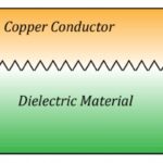
External connectors maintain signal integrity by reliably transmitting data between various electronic components and systems without loss of fidelity.
In this article, we discuss the importance of signal integrity, review high-speed deployment challenges, and highlight various connector design strategies to prevent distortion and degradation.
Understanding connector signal integrity challenges
Unchecked signal integrity issues caused by faulty connectors can lead to bit errors, data corruption, and even system failure. The consequences of signal integrity lapses are particularly severe for mission-critical applications such as advanced driver assistance systems (ADAS), medical devices, and aerospace or military equipment.
In data centers, maintaining signal integrity is essential for high-speed terabit Ethernet (TbE), as connectors are required to preserve signal clarity over extended frequencies and distances.
Crosstalk, whether near-end crosstalk (NEXT) or far-end crosstalk (FEXT), is one of the most common signal integrity issues. It typically occurs in densely packed connectors where conductive path proximity creates susceptibility to overlapping electromagnetic fields. Impedance mismatch, another top signal integrity challenge, is caused by discrepancies between source, connector, cable, and load. This mismatch disrupts the efficient transfer of energy, leading to attenuation, signal distortion, and return loss.
Insertion loss stems from signal strength reduction due to absorption and reflection within a connector. At higher frequencies, this loss becomes more pronounced, significantly diminishing the signal-to-noise ratio (SNR) and adversely impacting overall system performance. Notably, insertion loss varies based on physical connector properties, including material composition and internal structure, as both directly influence signal propagation.
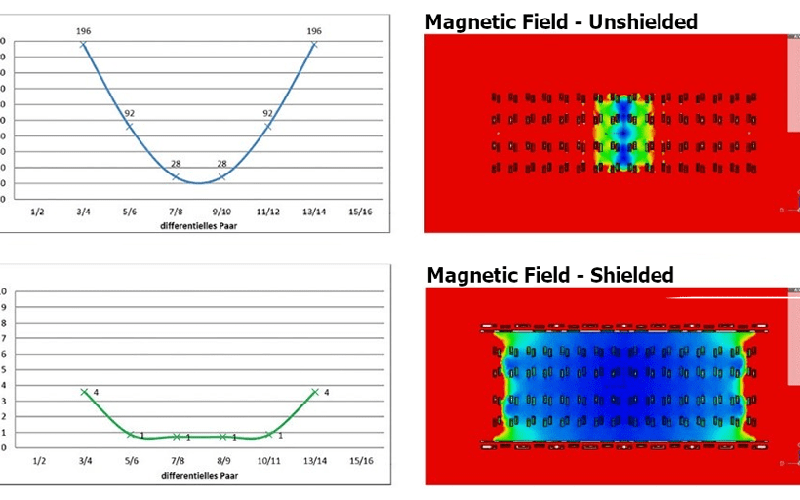
Figure 1. Comparative simulation results show magnetic field intensity around an electrical connector: the upper graphs and image illustrate the field in an unshielded scenario, while the lower graphs and image depict the field when shielded, demonstrating significantly reduced magnetic interference (Image: ept GmbH via Connector Supplier).
Moreover, connectors are susceptible to electromagnetic interference (EMI) and radio frequency interference (RFI). These ubiquitous signals originate from electrical devices, radio waves, and even nearby cables or connectors. EMI/RFI can significantly disrupt the integrity of signals transmitted through connectors and cables, leading to data loss or corruption. EMI/RFI interference is particularly problematic in high-density electronic environments where multiple devices operate simultaneously.
Maintaining connector signal integrity
Proactive design measures are essential in effectively addressing connector signal integrity issues. Optimizing the spacing and arrangement of conductive paths, for example, minimizes electromagnetic field overlap and crosstalk.
Similarly, precisely engineering key components and selecting connector material to match specific impedance characteristics mitigates the effects of return loss while reducing mismatch. Additionally, connectors with low absorption and reflection properties decrease insertion loss, while strategic pin arrangement and shielding help maintain signal integrity over a wide frequency range and prevent EMI/RFI exposure.
Testing also plays an important role in ensuring connector signal integrity. Time-domain reflectometers and network analyzers, for example, help system designers eliminate issues such as crosstalk and impedance mismatches. These instruments precisely measure reflection and transmission characteristics under different conditions and in various scenarios. Vector network analyzers provide detailed information on connector frequency responses, while spectrum analyzers detect and analyze EMI and RFI impact.
Simulation tools assist engineers in fine-tuning connector design parameters, including shielding effectiveness and layout. These tools accurately model thermal effects and mechanical stress within connectors, factors that significantly impact long-term signal integrity. Additionally, simulations facilitate electromagnetic field distribution (EMF) assessment within connectors to identify potential areas of signal leakage or interference.

Figure 2. A detailed connector model depicted with a rainbow heatmap illustrates the distribution of surface currents across the connector’s geometry (Image: Dassault Systems).
Simulating real-world environmental conditions helps engineers customize connector designs for specific operational scenarios or multi-purpose applications. Finite element analysis (FEA) and computational fluid dynamics (CFD) tools are also employed to predict connectors’ performance under thermal and mechanical stress. Electromagnetic simulation software further helps optimize the design of EMI/RFI-resistant connectors.
Lastly, adherence to industry standards set by the IEEE, IEC, or JEDEC is essential in high-speed connector design. Compliance with these standards ensures connectors meet established criteria for performance, safety, and interoperability.
Trends in high-speed connector design
Connector design, especially for high-speed applications, is continuously evolving, focusing on new materials and architectures. Key trends include:
- Nanomaterials: Improved electrical and thermal properties reduce signal loss and bolster connector durability. Moreover, the unique molecular structure of nanomaterials facilitates the design of smaller, more efficient connectors that withstand higher frequencies and greater electrical loads. Graphene and carbon nanotubes, for example, can potentially offer exceptional conductivity and mechanical strength.
- Modularity: Connector designs with modularity provide flexible configurations, adapting easily to various application requirements and simplifying maintenance and upgrades. Modularity offers easy integration of various connector types and sizes within a single system.
- Shielding: Multi-layered shielding techniques using materials such as copper, aluminum, nickel, and conductive polymers effectively mitigate the effects of EMI/RFI and electrostatic discharge (ESD).
- Heat dissipation: Employing conductive materials, optimized layouts, and heat sinks is key to maintaining optimal operating temperatures and reducing thermal stress.
- Smart connectivity: Self-diagnosis and real-time performance monitoring capabilities facilitate proactive maintenance and ensure optimal connector performance.
Summary
Unchecked signal integrity issues can lead to bit errors, data corruption, and even system failure. While all electrical signals are susceptible to interference and degradation, effective design and materials significantly reduce and mitigate these effects. In high-speed or crowded electronic environments, well-designed external connectors are crucial for maintaining signal integrity and reliable data transfer between different components and systems.
References
The Truth About High-Speed Connector Design, Signal Integrity Journal
Signal Integrity is Key to Today’s High-Speed Connectivity Designs, Connector Supplier
All Things Connectors: High Speed and Bandwidth, Cadence
How to Design Connectors and Cables for Signal Integrity, Sierra Circuits
High-speed Connector Design with Modeling and Simulation, Dassault Systems