Most antenna designs operate via the resonance principle, which is based on the fact that electrons moving through a conductor reflect back toward the power source when encountering a discontinuity. When current, caused by a radio signal’s induced voltage, reaches the end of the antenna element, it is reflected, travels in the reverse direction, and undergoes a 180° change in phase. If the conductor is a quarter of a wavelength long, current from the input will experience a 90° phase change as it traverses the conductor, then reflect through 180° and 90° additionally during the return trip.
The 360° total phase change restores the signal to its original form, creating a standing wave. This standing wave corresponds to the operating frequency. Other resonant antenna designs are three-quarters of a wavelength long and this principle is valid for other odd multiples of the quarter wavelength. Such antennas are termed “harmonically operated”.
The physical dimensions of the antenna are critical. Most antennas in use today are what are called electrically short antennas meaning their dimensions are less than that of the wavelength for the frequency they radiate. In general, electrically short antennas have electrical qualities that are more sensitive to antenna dimensions than their larger counterparts. So it is useful to review the effects of antenna dimensions on antenna qualities since these factors enter into design and measurement scenarios.
 The most fundamental form of antenna is the dipole with the half-wave dipole being most common. It consists of two radiating elements each about a quarter-wavelength long. Its input impedance at resonance is between 50 and 70 Ω depending on its length/diameter ratio. As with other resonant antennas, the current distribution on the dipole is
sinusoidal. Its three-dimensional radiation pattern in the E-plane (a reference plane along which the dipole axis lies) looks like the number eight while the radiation pattern in planes perpendicular to its axis (H-plane) is uniform.
When used for receiving or transmitting frequencies some distance from that for which they are tuned, conventional dipoles experience some issues. Perhaps most significant is that the antenna input impedance strongly depends on the antenna’s length-to-wavelength ratio. So impedance matching issues arise when the antenna operates far from the half-wave resonance frequency. The behavior is particularly true for a thin dipole, where the ratio of length-to-diameter is large. Reducing the ratio also reduces the amount of mismatch.

Also of note is that a balanced antenna such as a dipole is usually connected to an unbalanced (or coaxial) cable by means of a balun. The term balun comes from the combination of balanced and unbalanced. It is basically a special kind of transformer. Without a balun, skin currents form on the outer conductor of the coaxial cable which can cause strong electromagnetic interference or significantly alter the antenna radiation pattern.
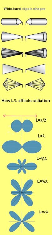
Given that thin dipoles have impedance matching issues that worsen for frequencies farther away from resonance, one way to mitigate the problem is to thicken-up the radiating elements. This is the approach used for broadband dipoles. Broadband dipoles are often designed in the form of a cage to minimize material use. Another commonly used broadband test antenna is the biconical antenna.
Another point to note is that above the full-wave resonance point, the dipole radiation pattern changes as a function of the antenna length-to-wavelength ratio. The effect can be so severe that there may be no primary direction of radiation. The behavior arises from the non-ideal current distribution on the dipole at large length-to-wavelength ratios.
A common way of addressing the problem is to alter the current distribution on the antenna by adding reactive elements, ferrite rings, or similar items that effectively allow only part of the antenna to radiate at higher frequencies. The point is to keep the ratio of wavelength-to-antenna length almost constant though the frequency
varies.
That brings us to monopole antennas. Their operating principle is based on the fact that the current distribution on an antenna that is only a quarter-wavelength long is identical to that on a half-wave dipole if one of the dipole antenna elements is replaced by a highly conducting surface. This reflection principle gives vertical quarter-wave antennas sitting on conducting ground basically the same radiation pattern as half-wave dipole antennas. The monopole input impedance is half that of a dipole, exhibiting values between around 30 and 40 Ω
The conducting surface on which the monopole sits is critical. That’s why radio station transmitting antennas typically have a ground net of wires (commonly also called radials) buried around the antenna tower. A special form of a monopole is the groundplane antenna which is characterized by several wires or rods (known as radials) arranged radially from the feed point. These antennas typically use a down angle of about 135° to the quarter-wave monopole. The point is to boost the feed-point resistance to about 50 Ω for easy matching to commonly used coaxial cables.
Antenna directivity can be enhanced by adding additional elements, with or without direct electrical connection to the transmitter, receiver or antenna. Antennas that focus their radiated power in a particular direction are called directional antennas. Directional antennas see improved parameters that include gain, directivity, and those associated with the radiation pattern, like front-to-back ratio, side-lobe suppression or half-power beamwidth.
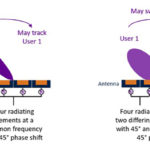
The simplest form of a directional antenna consists of two monopole antennas at a predefined distance, each fed with different phase. For example, consider two monopoles placed a quarter-wavelength apart where one is fed with a signal and the other receives the same signal but 90° out of phase. The far-field strengths generated by the two individual antennas add to produce a sharply defined null towards the backside which can effectively suppress interfering signals.
Similarly, superimposing the far-field patterns from two or more radiators arranged at defined distances and with defined phase shifts yields directional patterns with a directivity limited mainly by the space available for the
radiators. A point to note is that the radiators in directional antennas don’t typically have separate feeds. Generally only one radiator is fed from the cable and the remaining elements get activated by this radiator. Yagi-Uda antennas commonly used for receiving over-the-air TV and VHF sound broadcasts typically have between four and 30 elements and yield gain values of 10 dB and more.
 A special type of directional antenna is the log-periodic dipole antenna (LPDA). Here beam shaping is by means of several parallel dipoles of increasing lengths and spacing. Each dipole is fed out of phase to the element on either side by a common feed line. The angle α formed by the lines joining the dipole ends and by the longitudinal axis of the antenna remains constant, as well as the ratio of the lengths of neighboring elements and their spacing.
This LPDA is characterized by active and passive regions. The antenna is fed starting at the front (i.e. with the shortest dipole). The electromagnetic wave passes along the feed line, and all dipoles that are markedly shorter than half a wavelength don’t radiate. The dipoles in the half-wavelength range are brought into resonance and form the active region, which radiates the electromagnetic wave back in the direction of the shorter dipoles. Thus the electromagnetic wave doesn’t reach the longer dipoles located behind the active region. The active region usually consists of three to five dipoles, and its location varies with frequency.
The lengths of the shortest and longest dipoles of an LPDA determine the maximum and minimum antenna frequencies. Because only some of the dipoles contribute to the radiation at a given frequency, the directivity (and thus the gain) with 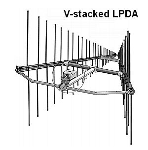 LPDAs is relatively small in relation to the overall size of the antenna. But the advantage of the LPDA is its large bandwidth. The radiation pattern of an LPDA is almost constant over the entire operating frequency range. In the H-plane it exhibits a half-power beamwidth of about 120° while the E-plane pattern is typically 60° to 80° wide. The beamwidth in the H-plane can be reduced to about 65° by stacking two LPDAs in a V-shape.
It should be noted that antennas for frequencies in the upper gigahertz range and above may employ horns and waveguide-type radiators rather than conventional antennas. Additionally, electromagnetic metamaterials are starting to be used for electromagnetic waves in this frequency range. Metamaterials are specially designed materials having structural features that interact with frequencies of interest. For microwave radiation, the features are on the order of millimeters. Microwave frequency metamaterials are usually constructed as arrays of electrically conductive elements (such as loops of wire) that have suitable inductive and capacitive qualities. These radiating elements typically look nothing like conventional antennas. In a nutshell, they basically store and release energy, rather than just radiating energy, in a manner that lets them behave as an antenna would.