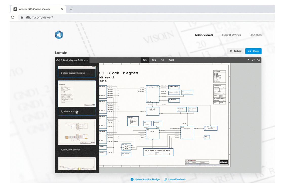
Altium has launched a new cloud-based application that redefines the way that printed circuit board designs are shared between designers, part suppliers, and manufacturers.
The A365 Viewer, powered by the Altium 365 cloud platform, is a brand new, and innovative way to view and share electronic designs through a browser on any web-enabled desktop, phone or tablet. Schematics, PCB layout, and 3D visualization provide an interactive eCAD experience with no downloads or installations required. The A365 Viewer is part of Altium’s cloud strategy and newly launched Altium 365 cloud platform.
 Until now, designers have been forced to share their PCB designs through PDFs or static images. With the new A365 Viewer, an interactive experience is created that retains all of the key relevant information that’s typically lost when sharing static files. For example, the A365 Viewer allows users to search for, select, cross-probe and inspect components and nets while moving seamlessly between schematic, PCB and 3D views of their board.
Using the A365 Viewer requires no CAD tools or experience. The A365 Viewer is designed to work with multiple eCAD formats, currently supporting Autodesk®️ Eagle™ and Altium Designer™. Other popular PCB design software formats will be supported in the near future.
Anyone can easily embed the viewer on their website, free of charge, by visiting https://www.altium.com/viewer/ . As an example, a well-known developer of electronics hardware and software kits, Arduino, is helping engineers and makers to easily and quickly visualize the PCB designs and assemblies available in their product kits, by embedding the A365 Viewer on the Arduino website.
The A365 Viewer protects the IP rights of design owners while retaining the CAD design details via a new process called Published Design Impression (PDI). The Viewer processes the design source files to create a Published Design Impression, or PDI. The PDI is a CAD-aware, perishable snapshot of the design that captures limited information such as components, net connectivity and basic geometrics, excluding design primitive data that would be required to fully comprehend and author changes to the design.
The design sources are discarded immediately after being used solely for the purpose of creating a PDI. The design is available for the duration of the user’s browser session and is automatically removed when the browser tab is closed.


