The Coriolis effect, a subtle and often-misunderstood principle of physics, has been adapted for highly accurate mass flowmeter instrumentation.
The first part of this article briefly explained the issues associated with accurate measurement of fluid mass and flow, a very common requirement in industrial, laboratory, and medical applications.
The Coriolis Effect, or “May the Effect Be With You”
The effect was not fully understood for many years, and leading scientists and mathematicians struggled to properly define it via varying interpretations (see Reference, “History of Meteorology”). It is named after French mathematician Gustave Gaspard Coriolis, who showed in the early 1800s that you must take into account an inertial force when you analyze the motion of bodies in a rotating frame of reference. From a physics standpoint, it is an effect and not a force and is the consequence of the interaction between a rotating body, frame of reference, and motion.
Whether you see it as a force or an effect depends on the observer’s frame of reference — which is why it gets both designations. The Coriolis effect exists only when using a rotating reference frame. It is mathematically deduced from the law of inertia. Hence it does not correspond to any actual acceleration or force, but only the appearance thereof from the point of view of a rotating system (the Reference from “New World Encyclopedia” is excellent on the math and physics)
Despite its various large-scale manifestations, it is also the basis for small-scale applications, including the precise measurement of the mass flow rate of fluids. Once again, innovators can see and devise new ways to solve long-standing problems by drawing on diverse and often seemingly irrelevant phenomena. The Coriolis effect, which is also called a gyroscopic result, has practical applications beyond bathtub drains and launch vehicles.
With sophisticated engineering, you can use it to measure the flow of material, or mass flow, through tubes and pipes. A standard volumetric flowmeter is affected by changes in the temperature, as well as by pressure, density, viscosity, and the flow profile of the process fluid. By comparison, a Coriolis flowmeter provides a direct mass measurement that is unaffected by changing process fluid characteristics.
So, what about that bathtub water-drain direction and the Coriolis effect? Many people have heard that bathtubs drain clockwise in the Northern Hemisphere and counterclockwise in the Southern Hemisphere due to the Coriolis effect (Figure 1). This is not a myth, but this effect is very hard to set up as a valid experiment due to practical challenges. The tub must be circular, the water in it must be allowed to settle for days and be absolutely still with no surface or subsurface currents, and the small stopper must be pulled out slowly and steadily that does not induce a water-flow current, among the many other factors.
Measuring material flow
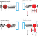
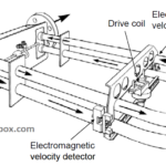
The conceptual Coriolis flow meter uses a U-shaped tube through which the fluid you are measuring, which can be liquid or gas, flows (Figure 2). The flow meter vibrates this tube at its resonant frequency using a capacitive, piezoelectric, or electromagnetic drive. The fluid travels through the tube, and the Coriolis force causes an angular deflection or twisting of the tube out its geometrical plane. As the fluid travels into and out of the tube, its inertia alternately reinforces and resists the oscillations that are imposed in the tube to cause the twist. The amount of twisting is directly proportional to the mass flow.
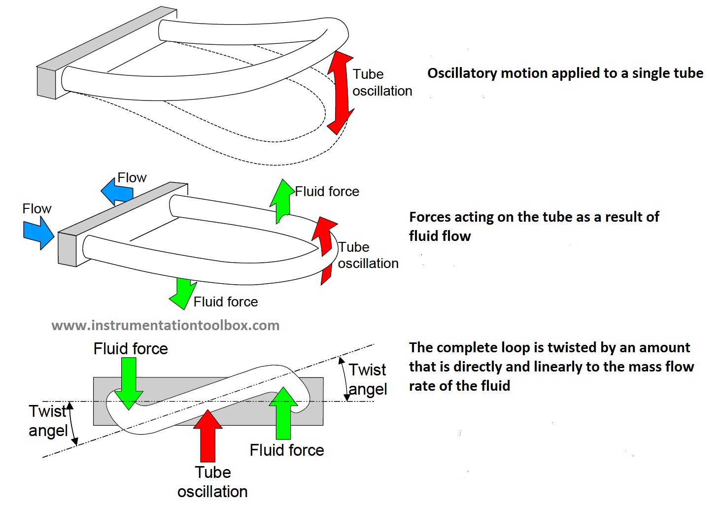
If you have trouble understanding how this effect happens, do this simple test: Take a garden hose, turn on the water, form a U-shaped loop between your hands, and then twist your wrists to make the end of the loop go up and down. You’ll see the loop twist out of the flat plane of oscillation as the water flows. If you shut off the water flow, the loop doesn’t twist as you make the same motions.
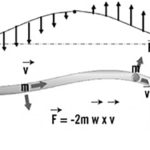
Vector physics can quantify the situation. The vector Coriolis force is: Fc=2mω×v, where m is the mass, ω is the (vector) angular velocity of the rotation axis, × is the vector cross-product operation, and v is the (vector) particle velocity relative to the rotation axis. The mass flow rate, q, is then proportional to the twisting, or deflection angle, θ, of the tube and is inversely proportional to the angular velocity, ω, of the tube: q=KSθ/(4ωL r), where KS is the angular spring constant of the tube, L is the effective length of the tube, and r is the distance between the tube and the central axis. You can determine the mass flow by measuring the resonant frequency and the twisting angle, for a given construction of the loop.
As an added benefit, the Coriolis design lets you determine the density of the fluid. Consider the vibrating system as a tube mass and a fluid mass with a natural spring-system frequency. If you continue the analysis, you’ll find that the fluid mass flow is proportional to the fluid density, and the density determines the tube frequency. Therefore, by monitoring the change in resonant frequency of the tube, you can precisely determine the fluid density.
The next part looks at Coriolis flow meters in more detail.
Related EE World Content
- ADI ups ante in high-precision MEMS gyros
- Gyroscopes, Part 2: Optical and MEMS implementations
- Mass Flow Meter Features High Pressure Resistance
- Global Market for Gas Flow Meters, Sensors, & Monitors to Reach $6.4B by 2019
- Watching fluid flow at nanometer scales
- What information does a proximal flow sensor provide?
Other References
- History of Meteorology, “The Coriolis Effect: Four centuries of conflict between common sense and mathematics, Part I: A history to 1885”
- New World Encyclopedia, “Coriolis effect”
- “A Micromachined Coriolis-Force-Based Mass Flowmeter for Direct Mass Flow and Fluid Density Measurement,” 11th International Conference on Solid-State Sensors and Actuators (ICSSSA), 2001
- Analog Devices, “Electromagnetic Flow Meters: Design Considerations and Solutions”
- Bronkhorst High-Tech B.V. “The Importance of Mass Flow Measurement and the Relevance of Coriolis Technology”
- Control Engineering, “Are Coriolis flowmeters a universal technology?”
- Control Engineering, “Tutorial: Coriolis mass flowmeters”
- Chemical Engineering, “Patent granted on microfluidic device design”
- Chemical Engineering Progress “Coriolis: The Direct Approach to Mass Flow Measurement”
- Chemical Processing, “Flow Meter Design: Bend It Like Coriolis”
- Instrumentation and Control, “A history in Coriolis flowmeter technology – and the future…”
- com, “How a Coriolis Mass Flow Meter Works”
- Fierce Electronics, “A Review of Your Flow Sensing Options”
- Fierce Electronics, “An Overview of MEMS Inertial Sensing Technology”
- Flow Measurement and Instrumentation, “Flowmetering of non-Newtonian liquids”
- National Ocean Service, “Currents: The Coriolis Effect”
- University of Liverpool, “Experimental investigation into non-Newtonian fluid flow through gradual contraction geometries”
- Universal Flow Monitors, Inc. “Coriolis Mass Flowmeter Technology”
- Water Online, “3 Dirty Little Secrets About Coriolis Flow Meters”