• Skip to primary navigation
  • Skip to main content
  • Skip to primary sidebar
  • Skip to footer

Electrical Engineering News and Products

Electronics Engineering Resources, Articles, Forums, Tear Down Videos and Technical Electronics How-To's

  • Products / Components
    • Analog ICs
    • Connectors
    • Microcontrollers
    • Power Electronics
    • Sensors
    • Test and Measurement
    • Wire / Cable
  • Applications
    • Automotive/Transportation
    • Industrial
    • IoT
    • Medical
    • Telecommunications
    • Wearables
    • Wireless
  • Resources
    • DesignFast
    • Digital Issues
    • Engineering Week
    • Oscilloscope Product Finder
    • Podcasts
    • Webinars / Digital Events
    • White Papers
    • Women in Engineering
  • Videos
    • Teschler’s Teardown Videos
    • EE Videos and Interviews
  • Learning Center
    • EE Classrooms
    • Design Guides
      • WiFi & the IOT Design Guide
      • Microcontrollers Design Guide
      • State of the Art Inductors Design Guide
    • FAQs
    • Ebooks / Tech Tips
  • EE Forums
    • EDABoard.com
    • Electro-Tech-Online.com
  • 5G

Difference between a waveguide and transmission line

April 12, 2022 By dherres

As electronics migrates to higher and higher frequencies, the media routing electronic signals to their intended destinations grow increasingly exotic. This is particularly true as communication technology moves to 5G frequencies which are characterized by millimeter wave transmissions. In this frequency range, engineers are more likely to encounter waveguides and transmission lines rather than ordinary wiring.

transmission lines
Examples of transmission lines include microstrips and striplines. Microstrip conductors sit on the exterior layer of the PCB. They are surrounded by air and thus experience less dielectric loss than striplines. But traces on the PCB can radiate more energy than the stripline conductor sandwiched between two reference planes. With this layer stackup, narrower traces can provide the same impedance values as thicker microstrip traces on the PCB exterior. And the signals are better protected from EMI and noise by the double reference planes.

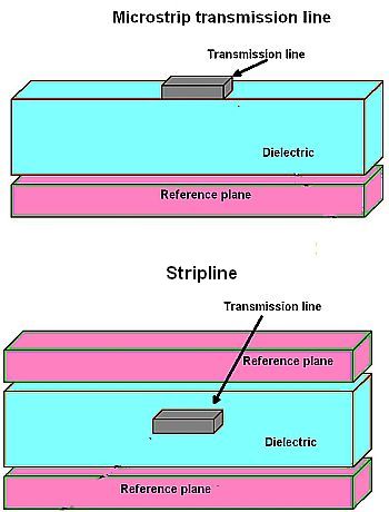
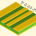
A transmission line is basically two or more conductors separated by an insulating medium. The insulating medium can be circuit board material, as in the case of microstrip lines. In the case of coax cable, the insulating media is the plastic material separating the center conductor from the outer shield.

The normal operating mode for a transmission line is TEM (Transverse Electromagnetic) or quasi TEM mode where neither the electric nor the magnetic field is in the direction of propagation. But a point to note is that all signal frequencies can pass through a transmission line.

A waveguide is a special form of a transmission line. Metal waveguides are typically one enclosed conductor filled with an insulating medium, normally air. More specifically, waveguides are typically hollow metallic tubes of uniform cross section for transmitting electromagnetic waves via successive reflections from the tube’s inner walls. Thus transmission lines like coax have a center conductor. Waveguides don’t. The tube wall provides distributed inductance. The empty space between the walls provided distributed capacitance.

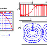
Waveguides handle TE (Transverse Electric) or TM (Transverse Magnetic) mode transmission—they can’t support TEM mode. In TE mode there is no electric field in the direction of propagation. TE mode transmissions are sometimes called H modes because there is only a magnetic field along the direction of propagation. In the TM mode the magnetic field is transverse to the direction of propagation while the electric field is normal to the direction of propagation.

waveguides
In TE10, the “1” indicates the number of half-wavelengths across the broad dimension of the electric field. The “0” indicates that the length of the narrow dimension is less than a half-wavelength of the magnetic field. Similarly, TE20 indicates two half-wavelengths fit in the longest dimension, and so forth.

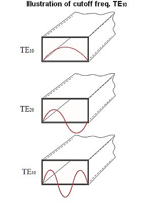
Thus where transmission lines can pass signals of all frequencies, waveguides can only pass frequencies above the TE or TM mode cut off frequency, the lowest frequency the waveguide can pass. The lowest frequency, in turn, relates to the longest half-wavelength that fits in waveguides’ biggest dimension. The exact mechanics for the cut-off frequency of a waveguide vary depending on its shape. Signals can progress along a waveguide via a number of modes. But the dominant mode is the one having the lowest cut-off frequency. For a rectangular waveguide, this is the TE10 mode. The equation for the cutoff frequency fc in a rectangular waveguide is fc = c/2a where c = the speed of light in the waveguide, m/sec; a = the largest internal dimension of the waveguide, m. The equation for a circular waveguide is fc = (1.8412×c)/(2πa) where c is as before and a = the waveguide’s internal radius, m.

Waveguides also differ from other transmission lines in transmission qualities. All waves travel through waveguides via reflections from the walls; in other transmission lines there are relatively few reflections during normal operating modes. A transmission line has a characteristic impedance but waveguides have a wave impedance. Thus circuit theory predicts how signals propagate through non-waveguide transmission lines; but field theory predicts propagation through waveguides. And if you want to transmit high power in a transmission line, you use a larger wire; but the dimensions of waveguides are determined by the propagation modes to be allowed, not by power levels.

Finally, in ordinary transmission lines waves don’t disperse, but they do in waveguides.

Waveguides are often the preferred method of handling microwave frequencies because microwave energy experiences less loss when traveling through waveguides than when traveling through coax. Additionally, waveguides are relatively easy to make and can handle power levels in the kilowatt range.

You may also like:

  • impedance
    The basics of VSWR and impedance, Part 1

  • Attenuation networks and their measurement

  • mmWave signals: The effect on PCB traces, cables and connectors

  • What are RF waveguides? Part 2: implementation and components

  • What are RF waveguides? Part 1: context and principles

Filed Under: Applications, FAQ, Featured, Telecommunications, Test and Measurement Tips, Wireless Tagged With: FAQ

Primary Sidebar

EE Training Center Classrooms

EE Classrooms

Featured Resources

  • EE World Online Learning Center
  • CUI Devices – CUI Insights Blog
  • EE Classroom: Power Delivery
  • EE Classroom: Building Automation
  • EE Classroom: Aerospace & Defense
  • EE Classroom: Grid Infrastructure
Search Millions of Parts from Thousands of Suppliers.

Search Now!
design fast globle

R&D World Podcasts

R&D 100 Episode 8
See More >

Current Digital Issue

June 2022 Special Edition: Test & Measurement Handbook

A frequency you can count on There are few constants in life, but what few there are might include death, taxes, and a U.S. grid frequency that doesn’t vary by more than ±0.5 Hz. However, the certainty of the grid frequency is coming into question, thanks to the rising percentage of renewable energy sources that…

Digital Edition Back Issues

Sponsored Content

New Enterprise Solutions for 112 Gbps PAM4 Applications in Development from I-PEX

Positioning in 5G NR – A look at the technology and related test aspects

Radar, NFC, UV Sensors, and Weather Kits are Some of the New RAKwireless Products for IoT

5G Connectors: Enabling the global 5G vision

Control EMI with I-PEX ZenShield™ Connectors

Speed-up time-to-tapeout with the Aprisa digital place-and-route system and Solido Characterization Suite

More Sponsored Content >>

RSS Current EDABoard.com discussions

  • Unusual gap shape of ETD59 ferrite core?
  • Vco cadencd
  • WH-LTE-7S1 GSM module and SIM card problem
  • Effect of variable gain amplifier and LNA on the input RF signal's phase
  • Pic 16f877A Hex file

RSS Current Electro-Tech-Online.com Discussions

  • Very logical explanation on low calue C3
  • HV Diodes
  • intro to PI
  • Need help working with or replacing a ferrite tube
  • Help wanted to power an AC120v induction motor ( edited from Brushless motor - thank you @SHORTBUS= )

Oscilloscopes Product Finder

Footer

EE World Online

EE WORLD ONLINE NETWORK

  • 5G Technology World
  • Analog IC Tips
  • Battery Power Tips
  • Connector Tips
  • DesignFast
  • EDABoard Forums
  • Electro-Tech-Online Forums
  • Engineer's Garage
  • Microcontroller Tips
  • Power Electronic Tips
  • Sensor Tips
  • Test and Measurement Tips
  • Wire & Cable Tips

EE WORLD ONLINE

  • Subscribe to our newsletter
  • Lee's teardown videos
  • Advertise with us
  • Contact us
  • About Us
Follow us on TwitterAdd us on FacebookConnect with us on LinkedIn Follow us on YouTube Add us on Instagram

Copyright © 2022 · WTWH Media LLC and its licensors. All rights reserved.
The material on this site may not be reproduced, distributed, transmitted, cached or otherwise used, except with the prior written permission of WTWH Media.

Privacy Policy