The traditional model railroad power and control has transitioned from simple hardwired loops to advanced networking in the past decades, bringing many benefits and a few drawbacks.
Networking changes things (almost) completely
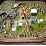
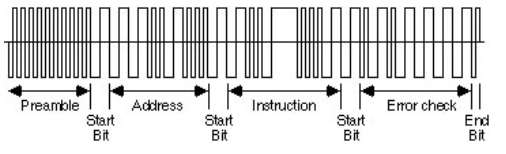
This scenario changed radically with the development of digital command control (DCC) for model railroads. What DCC did was bring data and networking to the track and system. The model industry and its vendors agreed in 1994 on an open standard which defined how to digitally encode signals via a unique ID for each engine via the track, which now also functions as the communications bus (Figure 1). The DCC specification defines wire gauge, voltages, formats, protocols, and more, including pulse-width modulation to encode the data due to its high noise resistance. The track would always have full voltage to power the engine. The modulated signals superimposed on the track convey instructions that direct each engine’s speed, direction, and other functions via an on-board decoder/motor controller.

The user operates the model railroad via a hardwired handheld controller connected to the track through an interface box in most cases (Figure 2). Some “walkaround” handheld controllers are wireless and connect to the track via an RF link and receiver and then to the interface box. Some DCC vendors now support the use of smartphones in place of a dedicated controller. Advanced modelers replace the handheld controller with a PC and then build layouts that are automated and run themselves to execute complex routing, traffic, and operational sequences.

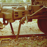
DCC has been a huge success and is now a standard feature or available option in all locomotives. It has also simplified cabling from a complex maze of individual wire loops from the multiple power supplies to each insulated rail block by going to a bus-oriented topology with dedicated wire paths (Figure 3).
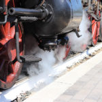
But the DCC success story doesn’t end there. Although originally intended primarily for engine control, vendors serving the modeling community realized it could solve another long-standing problem: adding realistic sound to the locomotive and layout operation. For many years, the way this had been done was to place various sound sources – small speakers driven by tape units or solid-state devices – around the layout, triggered by the train’s passing. It worked but was limited in what it could do, as a train going slowly would trigger the same sounds as one going quickly.
With DCC, all this changed. Manufacturers such as Soundtraxx developed decoders which are placed in the locomotive along with a tiny speaker and directed by digital codes sent by the layout operator. In this way, the engine sounds are localized as they should be and match the operation: slow, fast, loud, soft, chug, whoosh, and even features such as brakes squealing or couplers clanging. If you have ever seen a silent layout versus one running the full range of DCC-driven sound effects, the difference is dramatic and impressive.

Benefits get extended
But why stop there with DCC and networking? As a bus-networked topology, DCC can be used for much more. It is now being used for controlling dynamic lighting effects, track turnouts (also called switches), and accessories. It is even the interface to partially or fully computer-controlled layouts. Instead of a “rat’s nest” maze of wires with discrete, hardwired on/off loops to control each of these auxiliary functions, a single DCC bus can support them all. This is yet again a situation where the original intent of a standardized, well-constructed format became the starting point for extension into a much broader application. The original developers did not fully grasp how innovators would take this new set of tools and extend it to solve a related problem.
Of course, DCC is not without its headaches. As is often the case with networks and advanced technologies, there are two challenges. The first is getting through the initial configuration and set-up phase. Before a locomotive can be used, it must be set up with at least a dozen configuration variables. The full list runs to about 100 such variables; it’s the usual story of total flexibility and customization but requiring a lot of work to implement. This set is done via the DCC controller, with the locomotive either on a separate dedicated track or the idle mode’s main layout.
The second is the debugging problem when a formerly working system has problems. In fact, you can even now buy a network analyzer which decodes and displays the DCC codes, signals, their status, and more. It’s a very long way from the simpler hardwired cab-control scheme, which needed no setup and required only a voltmeter, ohmmeter, and wiring diagram to track down problems.
The next part of this story looks at an alternative to using rails to convey power, but which still has constraints and limits – at least for now.
Other References
- Model Railroader, “How to wire a layout for two-train operation”
- National Model Railroaders Association (NMRA), “Beginners guide to Command Control and DCC“
- Southern Digital, “How DCC Works”
- DCC Wiki, “DCC Tutorial — Basic System”
- CVPUSA, “The AirWire900™ Battery Powered Wireless DCC Control System”
- Wikipedia, “Connections” (TV series)

