The traditional model railroad power and control has transitioned from simple hardwired loops to advanced networking in the past decades, bringing many benefits and a few drawbacks.
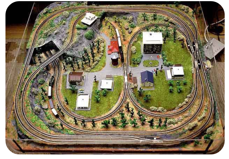
Anyone who ever had a basic model-railroad layout knows how easy it is to deliver power to the locomotive’s motor, as the physical rails (tracks) are also the power rails (Figure 1). The locomotive wheels – with the left side insulated from the right side – pick up the power and deliver it to the motor via small metal “brushes.” (Note that this power arrangement does not apply to Lionel’s legendary 027 trains and track, which uses a very different track and power arrangement.) Adjusting engine speed is simply a matter of controlling the voltage and polarity on the rails.
While this seems straightforward and certainly works, there are two long-standing problems: first, at low voltages, motor and pulling-power performance in terms of torque and fine-speed control is poor, since motors designed for 10 to 20 V don’t work well at one to two volts. This problem was overcome several decades ago through the use of the well-known pulsed-power technique, where pulse-width modulation (PWM) of the full voltage is used instead of simply decreasing the rail voltage; there are videos of locomotive models pulling long strings of cars smoothly at under an inch/minute speed– a good demonstration of both low-end control and power.
More locomotives, new problems
The second and bigger problem occurs when trying to run more than one locomotive on the same set of tracks. Obviously, all motors will see the same voltage, and so having one engine go fast while another crawls is a recipe for crashes, and any voltage change affects all engines on the track. The solution is called “cab control,” where the track is physically divided into electrically isolated blocks and then allow only one engine in a block at any time (Figure 2).

As the train moves along, the layout operator must manually switch power from that engine’s supply to the next block via a single-pole, double-throw (SPDT) toggle switch; of course, you need one power supply per locomotive to do this. In effect, the supply “follows” its designated engine by the layout operator’s action switching it from block to block.
This certainly works, but it is challenging to keep up with if there are more than a few trains moving at the same time on the layout. Various schemes were worked out with automatic block-occupancy detection and power switchover, but they were costly but awkward (to be polite) despite their cleverness. Also, reliably detecting that a train is in a given block to initiate automatic switchover turns out to be a non-trivial problem in itself; it is usually done using optical blocking or via a “current-leak” detector across the rails.
Further, dividing the track into these electrically separate blocks takes effort and is difficult to change physically. It requires cutting small gaps in both rails at the same spot, then gluing a small plastic tab in the gap to ensure the break’s ongoing integrity; a medium- to large-size layout could have tens of such isolated blocks and gap pairs. On the other hand, all it takes to set this up is minimal “electrical” skills and hardwired point-to-point loops. At the same time, troubleshooting requires only a voltmeter and an ohmmeter – and labeled wires along with the wiring documentation, of course.
The next part of this article looks at the impact of networking on model railroading.
EE World Related Content
- Electric locomotives and catenary power systems – Part 1: basic functions
- Electric locomotives and catenary power systems – Part 2: power needs
- Electric locomotives and catenary power systems – Part 3: power delivery
- Electric locomotives and catenary power systems – Part 4: maintenance and corona
- Westinghouse and the fail-safe train air brake, Part 1: The problem
- Westinghouse and the fail-safe train air brake, Part 2: The solution
- Westinghouse and the fail-safe train air brake, Part 3: Electric brake control
- Westinghouse and the fail-safe train air brake, Part 4: Post-Westinghouse
- Sorry, but it’s “Goodbye, Caboose” – EoT devices have made you obsolete, Part 1
- Sorry, but it’s “Goodbye, Caboose” – EoT devices have made you obsolete, Part 2
- Electrified Locomotives, Tunnels, and the Pennsylvania Railroad: Astonishing engineering but a partially sad ending, Part 1: The challenge
- Electrified Locomotives, Tunnels, and the Pennsylvania Railroad, Part 2: The tunnels
- Electrified Locomotives, Tunnels, and the Pennsylvania Railroad, Part 3: The station
Other References
- Model Railroader, “How to wire a layout for two-train operation”
- National Model Railroaders Association (NMRA), “Beginners guide to Command Control and DCC“
- Southern Digital, “How DCC Works”
- DCC Wiki, “DCC Tutorial — Basic System”
- CVPUSA, “The AirWire900™ Battery Powered Wireless DCC Control System”
- Wikipedia, “Connections” (TV series)

