Today’s huge ac grids consist of many separate generators with new ones continually coming on line. When a generator is powered down for maintenance or even temporarily disconnected, it must resynchronize upon rejoining the grid, generally by automatic means with manual backup instrumentation in place if needed.
The process of synchronizing ac power sources to grid voltage has become more important with the spread of renewable energy. The power that wind and solar arrays generate must ultimately feed into the grid at frequencies closely matching that of the grid power. Here are a few basics of the procedures involved.
Utility generators on the U.S. utility grid generate power at 60 Hz ±0.5 Hz. Changes in utility frequency happen as a consequence of changing loads. Loads that cause more than a half-hertz dip in frequency cause automatic load shedding or other actions to bring the frequency back up.
When a relatively small ac generator connects to an operating grid, the waveforms of the two sources must synchronize. Specifically, they must match in voltage, frequency, phase, and phase sequence. And, of course, they must both be sine waves. In the case of phase, “synchronization” is defined as being within one electrical degree of the grid phase.
Synchronization is established with the individual generator still electrically isolated. Another requirement for ac synchronization of rotating generators is that generators added to the grid must have the proper droop speed (that is the difference between rated rpm and actual speed) so the shared load is in correct proportion to their respective ratings. The droop speed applies to the prime mover. This is a necessary requirement because the loading of a generator reduces its speed, which in turn precisely determines the frequency. It is possible for generators connected in parallel to rotate at incrementally different speeds because the output frequency of each is also a function of the number of poles.
To synchronize a single ac generator into an operating network, one must manipulate the new unit so its voltage and frequency are a close match to the overall network. Then the generator can be electrically connected. When connected, it will automatically lock onto the larger network and thereafter maintain synchronization without further adjustment. When a single small generator connects to a larger grid, every constituent generator changes its frequency output slightly to accommodate the added member, which adjusts to a far greater degree.
There are over 500 individual utilities supplying the North American grid, some having extensive banks of generators, all synchronized. The grid is divided into several segments, connected by high-voltage dc links, obviating the need for these large ac segments to synchronize with one another.
Separate generators intended to run in parallel generally connect through circuit breakers which also function as manual or power-operated switches. The contacts are designed to snap shut and to open quickly to minimize arcing. Three-phase systems require three-pole breakers.
If the breaker is closed and the rotor speed is not a close match, the unit with the higher rotational force abruptly pulls the weaker machine (with higher internal impedance) toward it in terms of RPM. The result is a sudden acceleration or deceleration, accompanied by heavy current in both the conductors joining the machines and in both machines’ windings. This shock to the system is also felt by both prime movers, perhaps in diesel motors breaking the crankshafts.
Additional effects may show up throughout the distribution system, including abrupt power supply oscillations, transformer damage and tripping of over-current devices causing power outages.
Improper phase matching results in the same high current and equipment damage, typically more severe than following improper frequency matching. Improper voltage matching causes high reactive power in the generator and severe mechanical shock to the rotor and stator, possibly pulling it loose from its mounts.
In the first decades of large electrical distribution systems, the synchronization process was primitive by today’s standards but nevertheless quite successful. Three incandescent light bulbs were connected between the three-phase generator’s terminals and the system terminals, one in each pair of legs. Operators slowly brought the generator to be added up to speed, observing the bulbs. They would flicker at a rate corresponding to the frequency difference between the new generator and that of the larger operating network. When there was a match, the bulbs would go dark, indicating no difference in frequency. The operator would then close the three-pole switch and the new generator would be added to the system and remain synchronized.
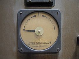
An example of a synchroscope.
An alternate method of synchronization, also manual, makes use of an instrument known as the synchroscope. The synchroscope consists of a two-phase stator. The two stator windings are at right angles to each another. A phase-splitting network lets the current in one phase lead the current of the other phase by 90°, thereby generating a rotating magnetic field. The stator windings connect to the generator being synchronized. A polarizing coil is connected to the running generator.
The rotating element is unrestrained and can rotate through 360°. It usually consists of two iron vanes mounted in opposite directions on a shaft, one at the top and one at the bottom, and magnetized by the polarizing coil. If the frequencies of the incoming and running generators differ, the synchroscope will rotate at a speed corresponding to the difference. If incoming frequency exceeds the running frequency, rotation will be clockwise; if the incoming frequency is below the running frequency, the indicator will rotate in the counterclockwise direction. When the synchroscope indicates zero phase difference, the pointer is at the 12 o’clock position and the two ac generators are in phase.
For simplicity, the synchroscope is connected to only one of the three phases in each power source. This hookup reliably tests frequency and phase angle but not phase sequence. As a backup, the three lamps are deployed to verify phase sequence. All of this instrumentation operates at reduced voltage, derived from step-down transformers.
After the local power source is adjusted to match frequencies and phase angles, the smaller generator switches online. The smaller generator will automatically pull into step with the overall grid unless there is a significant phase difference.
Fully automatic synchronization originally depended upon electromechanical synchronizing relays. Currently, highly reliable microprocessors have taken over, although lamps and synchroscopes remain in place for monitoring and backup purposes.
A synchro check relay is inserted as an added precaution. It operates automatically to prevent interconnection in the event of excessive phase error.
All machines remain synchronized when the load changes within specific limits. An excessive change in system frequency, however, can cause constituent members to fall out of synch. Automatic disconnection then takes place, and this can cause a temporary power outage until the machines resynchronize.
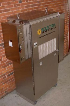
An example of a synchronous inverter, this one for a solar array
Renewable energy sources generate power via inverters that convert dc from, say, a solar array to dc. In the case of wind turbines, the turbine powers an ac generator whose frequency varies in proportion to wind energy. This varying frequency is generally converted to dc and then to constant-frequency ac that is grid compatible.
Of course, the connected ac must be synchronized to the grid. This takes place by means of a special kind of inverter called a synchronous inverter. Unlike an ac generator that is synchronized with another generator or into the grid, the synchronous inverter continuously samples the utility ac and synthesizes an output to match, copying the utility waveform with regard to voltage, frequency and phase angle.
The synchronous inverter is complex but the price has dropped as increasing numbers of units are sold.


It would be apt if the working principle of the SYNCHRONOUS INVERTOR is described and how it is different from a normal inverter
That’s why we provided this link in the article: https://www.testandmeasurementtips.com/7120/
“When there was a match, the bulbs would go dark, indicating no difference in frequency.” That is a correct but incomplete statement. It ALSO means that the phase is right, as well as the phase sequence. All bulbs dark means it is OK to close the switch. All bulbs on means the frequency is right, but the phase is not. The brighter the bulbs, the more out of phase the power. I am VERY conscious of this fact because…
When I was in engineering school in 1960, we had a power lab where we were expected to sync our motor-generator into the New York City power grid. One of the lab teams was either stupid (not likely in the third year of E-school) or curious (“I wonder what would happen if…”). They got the bulbs to be constant, but all full bright rather than all dark. that meant the frequency was perfect but the phase was bass-ackwards. The resulting transient snapped two bolts holding the motor-generator to the building’s frame, and blew a breaker that fed power to a couple of city blocks, including one not on the college campus.
All I can say is I wish YouTube had existed back then………………
Thanks for the additional information the sync lights Dave.