5G’s Orthogonal Frequency Division Multiplexing (OFDM) brings with it a major design challenge, namely an inherent wide dynamic variation between a signal’s peak and the average power. The peak-to-average power ratio (PAPR) leads to inefficient transmission performance. That’s because the OFDM waveform is created by the sum of multiple sinusoidal signals that can exhibit constructive and destructive behaviour. As a result, at some time instances, the ratio between the maximum signal power to its average will become high. A signal with high PAPR will cause a power amplifier (PA) to operate in its non-linear region.
A high PAPR creates two problems. First, out-of-band distortion leads to adjacent-channel interference and spectral emission mask (SEM) violations. Second, in-band distortion degrades the throughput performance. To tackle these problems, a radio’s power amplifier (PA) needs to operate below its 1 dB compression point (P1dB). That backing off improves linearity at the cost of reduced PA efficiency. We need a PAPR reduction technique to let the PA operate at high efficiency while maintaining good linearity.
Several techniques that reduce the PAPR of the OFDM signal have been proposed. There are two main categories for these techniques: distortion-based methods, which result in out-of-band distortion, and distortionless methods. This article defines PAPR in more detail and introduces the techniques to reduce PAPR. The article will also discuss some of the challenges to reduce the PAPR in multi-operator network use cases.
PAPR theory
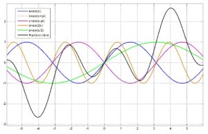
An OFDM waveform is created by the summation of multiple sinusoidal signals. Figure 1 shows that constructive interference between the sinusoids occurs when the individual sinusoids reach their maximum values at the same time. This constructive interference will cause the output envelope of the OFDM waveform to suddenly rise, producing high peaks generated from the constructive characteristic. At other times, destructive interference will occur. In that case, the individual sinusoids will cancel out one another, resulting in troughs in the OFDM waveform output envelope. Furthermore, in the example of Figure 1, the sinusoids are constant amplitude. The amplitudes of the sinusoids will, however, vary dynamically. This amplitude variation, combined with the destructive interference, results in a low average output envelope. Hence, the OFDM waveform features high PAPR.
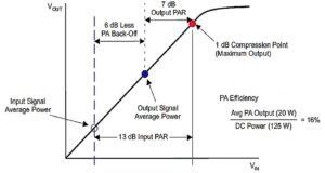
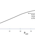
Figure 2. Peak reduction techniques can reduce PAPR, resulting in backing off power amplifier outputs.
As Figure 2 shows, when a multicarrier signal of very wide dynamic requirement with high PAPR such as an OFDM signal is fed into a PA, the PA operates in its nonlinear region. Doing so results in out-of-band distortion, which violates the spectrum emission mask (SEM), disrupts other adjacent channels, and creates unwanted radiation. At the cellular system level, this causes poor coverage, dropped calls, and low quality of service. Backing off the power to avoid PA compression will result in lower power efficiency and cell coverage. A promising solution would reduce PAPR. In Figure 2, the PAPR of the input signal is 13 dB. A PAPR reduction technique can reduce this to 7 dB, allowing 6 dB less back off, which results in a significant PA efficiency improvement.
High PAPR is a major practical problem involving multi-carrier signals such as an OFDM signal. If A = (A0, A1,…, A(N-1)) is a modulated data sequence of length N in time interval (0,t), where Ai is a symbol from a signal constellation and t is symbol duration, then the N carrier OFDM envelope is given by
where ω0 = 2πT and j =
-1
The PAPR of a transmitted signal, x(t) is the ratio of the maximum power and the average power of the signal and can be defined by:
 where E denotes the expectation operator, which calculates the signal’s average amplitude.
The other parameter to consider is crest factor, which is widely used in the literature, and is defined as the square root of the PAPR.
PAPR reduction Techniques
Until now, many techniques have been proposed to reduce high PAPR in communication systems. In general, these techniques can be separated into two categories, distortion-based and distortion-less. In the former category, some distortion that violates the spectral emission mask (SEM) will occur. Techniques such as clipping, noise shaping, peak windowing, and peak cancellation fall into this category. As the aim in the system design is to maximise efficiency, it can tolerate some distortion.
Distortionless techniques, sometimes called scrambling techniques, require some side information sent to the receiver device, adding complexity to the system. Moreover, this protocol is not defined by the 3GPP for user equipment. Techniques such as Partial Transmit Sequence (PTS) and Selected Mapping (SLM) fall into this category. These techniques are, however, not practical in 4G and 5G mobile systems. Hence, the distortion-based techniques are more attractive [1]. Here we review the peak cancellation technique used widely in wireless communication systems.
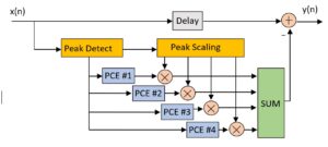
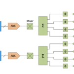
Figure 3. The peak-cancellation technique uses peak detection and filtering to reduce peaks created when peaks OFDM sinusoids align.
Peak Cancellation
Figure 3 shows the most promising PAPR reduction technique: peak cancellation (PC). Following the peak detection, the selected peaks are allocated to a peak cancellation engine (PCE). Each PCE gets the amplitude of the peaks and creates a scaling pulse by multiplying the peak phase by the filtered amplitude. Each PCE is occupied for the duration of the filter length and the incoming peaks should wait until the process of the PCE is completed. Finally, all the PCE outputs are accumulated and subtracted from the delayed input signal.
The PC’s main drawback is that it requires a minimum of two stages to achieve the required performance mandated in 3GPP. Hence, the complexity and latency will increase. The number of stages will increase for larger bandwidth and in multi carrier applications.
PAPR reduction challenges
Modern 5G systems present several challenges for PAPR reduction implementation.
Multi-band and multi-carrier
Increasing the number of component carriers (CCs) creates more peaks in the selected window in the time domain signal envelope. Those peaks cannot be compensated in one or two stages, requiring additional stages in the PAPR implementation. Especially in the inter-band carrier aggregation scenarios, where there is a large gap between the CCs, there will be several contiguous peaks in each selected window above the threshold. Applying the PC technique on these signals results in high error-vector magnitude (EVM). Selecting these peaks and applying filters requires more careful consideration to meet the EVM requirements. One technique to tackle this issue is proposed in [2].
Figure 4 shows the result of a clipped signal with conventional PC and with the proposed PC. Clearly, when there is no spacing between contiguous peaks in the selected window, as is the case in the conventional PC, peak regrowth occurs that can exceed the threshold. This results in spectral-emission violation and EVM degradation. The proposed PC results in suppressed peak regrowth because the spacing removes the possibility of overlapping in the finite impulse response (FIR) filter sidelobes.
Latency
End-to-end latency is one of the important factors in providing users with a quality experience, especially in 5G services such as ultra-Reliable Low Latency Communication (uRLLC). The peak cancellation technique requires several stages to reduce the high peaks in the signal. The latency contribution of the peak cancellation technique can be as high as 10 µs. That’s roughly 10% of the total latency specified in 3GPP Release 15.
Complexity
Increasing the number of stages in the peak cancellation can increase the complexity and the power consumption of the system. Particularly when implemented in an FPGA, the complexity of this implementation increases the system cost.
EVM
EVM is one of the imperative metrics to measure the quality of the transmitted signal in a base station. Implementing the peak cancellation results in a trade-off between the PAPR reduction capability and EVM performance. This is also important from the fact that greater PAPR reduction translates to better power amplifier efficiency. While achieving higher PAPR reduction is desirable, EVM performance requirement must still be met. Increasing the PAPR reduction means that the threshold level in the peak cancellation needs to be lower, which results in much larger number of peaks detected in a search window. To avoid EVM degradation and peak regrowth, only contiguous peaks at some distance from each other can be selected and passed through the peak engines. It is important to know that peak regrowth is created from the contiguous peaks. That’s because the input signal of the PC is an up-sampled signal and hence the contiguous peaks can exceed the threshold at the same time. The peak regrowth causes spectral leakage or out of band radiation and EVM deterioration.
Conclusion
Most communication systems require PAPR reduction. A high PAPR signal, once transmitted to a power amplifier, creates spectral regrowth that violates the spectral emission mask and deteriorates a network’s throughput performance. PAPR reduction techniques are that required to overcome this issue and increase power amplifier efficiency. Implementing PAPR reduction techniques in modern wireless systems requires careful consideration and some tradeoffs.
References
[1] P. Varahram et al., Power Efficiency in Broadband Wireless Communications, CRC Press, 2014.
[2] P. Varahram et al., Power amplifiers, US Patent, Patent number 20210184630, 2021.
Pooria Varahram is Research and Development Principal Engineer at Benetel. He holds a PhD in wireless communication systems from University of Putra Malaysia. His main expertise is in digital front-end and signal processing techniques.

