Designers who use inductive proximity sensors have a choice of high-performance signal-conditioning interface ICs, each offering different sets of features, functions, and capabilities.
In the two preceding features (see Related EEWorld Content), we looked at the inductive proximity sensor and its basic operation but did not look at the electronic interface circuit for this widely used sensor. This follow-up feature looks at three different ICs which are specifically designed for this sensor. It will not be a recitation of the specifications except for a critical few as needed, as you can read the linked data sheets themselves. Instead will focus on their functions, I/O, and other interesting features and capabilities.
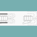
In inductive sensors with today’s circuitry and ICs, three coils are typically printed as copper traces on a printed circuit board (PC board), which may then be encapsulated for protection. They are arranged such that the transmitter coil induces a secondary voltage in the two receiver coils, which depends on the position of the metallic target above the coils. The signal which represents the target’s position over the coils is obtained by demodulating and processing the secondary voltages from the receiver coils. The target can be any kind of metal, such as aluminum, steel, or even a PC board with a printed copper layer.
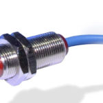
Due to its accuracy and precision, inherent ruggedness, convenient form factor, and ease of attachment, as well as flexibility in target being sensed, inductive sensors are used widely used in industrial applications and especially in automobiles for functions such as measurements related to motor rotation and position, high-temperature air/water valve position, electronic power-steering position and torque, transmission-gear position, throttle and brake position, and active suspension.
We will look at three representative ICs from Texas Instruments, Renesas Electronics, and Microchip Technology, all qualified to AEC-Q100 for automotive use. This is not an exhaustive list, as there are other vendors with ICs which can be used and even the cited vendors have other inductive-sensor interface ICs with different feature sets and specifications in their portfolios.
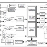
Texas Instruments LDC1101 1.8-V High-Resolution, High-Speed Inductance-to-Digital Converter
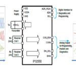
This 3-mm × 3-mm 10-pin IC is a 1.8-V to 3.3-V, high-resolution inductance-to-digital converter which is configured by a microcontroller using a 4-pin SPI interface (Figure 1). The LDC1101 includes a threshold-compare function which can be dynamically updated while the device is running. For measurement beyond basic presence detection, even sub-micron distance resolution is possible with the proper arrangement.

This device can be used to make two related inductance-sensor measurements:
- RP-measurement, which measures the equivalent parallel impedance of the sensor at its resonant frequency by measuring the energy loss of the sensor due to magnetic coupling with a conductive target.
- Inductance (L)-measurement, a measurement the resonant frequency of the sensor, which is a function of sensor inductance, also influenced by magnetic coupling with a conductive target.
The LDC1101 features dual inductive measurement cores, allowing for greater 150 kilosamples/second (ksps) 16-bit RP and L measurements simultaneous with a high-resolution L measurement which can sample at higher than 180 ksps with a resolution of up to 24 bits. The obvious question is: which one should you measure, or perhaps you should measure both? The answer is a function of many factors including, but not limited to, these:
- RP-measurements do not rely on an accurate reference clock and the device can perform RP-measurements without an external reference clock. This is an advantage in situations where a reference clock is not available, or where number of wires between the LDC and the microcontroller must be minimized.
- The effect of temperature drift of the target’s metal for L-measurements is small compared to the effect on RP-measurements. To account for the change in resistivity of the sensor conducting metal, temperature compensation is typically required for most applications that employ RP measurement.
- Most metal types can be equally well-measured with L or RP. However, there are some magnetic materials where the L response at certain frequencies is significantly smaller than the RP response. For those materials, RP is likely a more suitable choice.
The 59-page LDC1101 data sheet is detailed with specifications, configuration, and set-up information as expected. It also includes circuit analysis, modeling, and equations for setting various factors such as time constants, different sensing situations, size and material of different targets and how to accommodate them, and also links to many other relevant application notes and blogs.
The next part of this article looks at ICs from Renesas and Microchip Technology.
Related EE World Content
What are inductive proximity sensors? Part 1
What are inductive proximity sensors, Part 2
LVDT electronics, Part 1: Excitation and demodulation
LVDT electronics, Part 2: Interface circuitry
References
Texas Instruments
“LDC1101 1.8-V High-Resolution, High-Speed Inductance-to-Digital Converter” (data sheet)
“Inductive sensing: Should I measure L, RP or both?”
TIDA-00563, “Inductive Proximity Switch BoosterPack Reference Design”
Renesas Electronics
“IPS2200 Inductive Position Sensor” (data sheet)
Microchip Technology
“Robust, Low-Cost and Noise-Immune Motion-Sensing Inductive Sensors”
“LX3301A Inductive Sensor Interface IC with Embedded MCU”