by Ken Curt
The PCIe standard is ubiquitous among most all modern computing platforms. In notebooks, desktops and workstation PCs, PCIe is used to connect the CPU to graphics, Ethernet and various other controllers. PCIe enables connection of InfiniBand™ and Fibre Channel controllers in High-Performance Computing (HPC) systems. PCIe is used in telecom system, industrial control systems, instrumentation and many other applications. Thousands of different ICs, systems and device types use PCIe as their primary communication link.
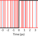
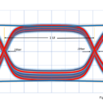
The latest version of the PCIe standard is PCIe 3.0 which specifies that each differential signal pair may operate at 8 Giga-bits-per-second (8 Gbps). A lane or link of multiple pairs is commonly said to operate at 8 Giga-Transfers-per-second (8 GTps). Basic physics shows that a transmitted signal gets degraded by the communications medium in which it travels (copper trace or wire for an electric signal, air for radio/TV, etc.). As a result, the signal that the receiver gets can be much different than what was transmitted. This is diagrammed in Figure 1 for a copper trace on a printed circuit board (PCB). If the signal degradation is substantial, there will be communication errors and reduced performance, or even a complete communication failure. At signal speeds of 8 Gbps, critical signal degradation occurs after just a few inches of printed-circuit-board (PCB) trace – sometimes just 10 to 12 inches (250 to 300 mm).
The copper signal traces on server boards are often 24-inches or larger, with the electrical connection to a backplane in a large chassis even longer, making it a challenge just to get an 8 Gbps signal from a CPU at one side of the board to another component at the other side.
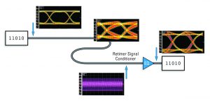
Many systems designs require PCIe signal traces much longer than 10, 12, or 16-inches to connect devices, and the signal channel often needs multiple PCBs and connectors. IDT has developed a PCIe 3.0 Retimer product family specifically for extending the distance of 8 GTps communication across longer PCB traces and multiple connectors. The Retimer can recover a very poor quality signal and will retransmit the signal that is as good as, and sometimes even better than, the original transmitted signal.
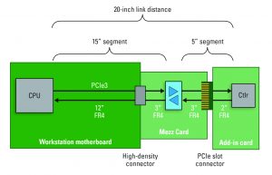
One example of the use of a Retimer is diagrammed in Figure 2. In this example, the target requirement is for the 8 GTps PCIe 3.0 signal to travel across 20-inches of FR4 PCB traces and two connectors, between the CPU and endpoint controller. Both upstream and downstream signal channels are shown (for 1-lane), and unless both the CPU and the endpoint can both support this distance the link will be unreliable. This distance is beyond normal PCIe 3.0 standards, and because there is an “open” PCIe 3.0 slot which can accept any add-in card, then all cards that could be used here must support this long link. Since it is impractical to insure that all cards will work well across this distance (including cards not yet designed), using a Retimer to break the channel into two shorter segments, of 15” and 5” as shown, is an easy solution. The Retimer features large transmitter drive, and an enhanced sensitivity receiver which enables reliable communications across traces which are longer than the standard limits, on both sides of the Retimer.
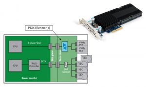
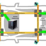
IDT’s PCIe 3.0 Retimers are used in many system applications including servers and workstations, storage systems, High-Performance Computing (HPC) platforms, telecom, instruments, embedded and industrial control boards, as shown in Figure 3. IDT’s PCIe 3.0 Retimers resolve difficult Signal Integrity (SI) problems resulting from very high speed communication over long distances.

What is a PCIe 3.0 Retimer?
Now that we have seen some common applications for a PCIe Retimer it is reasonable to ask: “Exactly what is a PCIe 3.0 Retimer, and how is it unique”? A Retimer produces a new data output signal which is synchronized to a clock input signal used for timing reference. These Retimers are also classified as “signal conditioners” because they provide signal conditioning of the high-speed differential Rx and TX signals. But be careful not to confuse these Retimers with signal conditioners for environmental sensors measuring temperature and pressure which are low-speed and very different in almost all functions.
Figure 4 is a block diagram showing one data channel in an 8 GTps PCIe 3.0 Retimer signal conditioner. To capture a small fast Rx signal there is a very sensitive Analog Front-End (AFE). The AFE includes a Continuous Time Linear Equalizer (CTLE, analog) that compensates for channel attenuation, and is the first stage of signal conditioning. The CTLE is followed by a Clock Data Recovery (CDR) circuit and Decision Feedback Equalizer (DFE, digital). Next, the digital signal is de-serialized, processed and re-serialized fortransmission. The transmit driver (buffer) which implements a multi-tap Finite Impulse Response (FIR) filter is the final stage of equalization and adds de-emphasis, boost and pre-shoot to the signal in order to pre-compensate the signal for channel loss.
To support the data channel there are configuration, control and status circuits. There is a Loss-Of-Signal (LOS) detector to determine if there isn’t a valid input signal or not. There is a receiver detection circuit to indicate whether there is a device attached that is capable of receiving data. There are also circuits for snooping incoming data packets to (1) support the automatic equalization procedure, (2) watch for power management changes, (3) catch error and/or lane-reductions, (4) identify attach/de-attach and (5) other system events that may affect channel operation. The Retimer is instrumented, with the ability to measure and report the input signal characteristics (needed as part of the equalization procedure). The Retimer can measure bit-error-rates, and has the ability to perform automatic power-on self-calibration so that it is set to work optimally every time.

These Retimers implement leading-edge physical IO capabilities and match or exceed the capabilities of its link partners. Clearly, PCIe 3.0 Retimers are very sophisticated devices and are neither like simple redrivers, nor the much, much simpler data buffers (saturating amplifiers) of your parent’s era.

New systems designs are either replacing the traditional rotating Hard Disk Drive (HDD), or complementing HDDs with much, much faster SSDs. The highest performance SSDs from Intel and others have been designed with a link width of four lanes of PCIe 3.0, giving 8 GByte-per-second raw link bandwidth capacity (8 Gbps/channel x 4 channels x 2 channels/lane (full-duplex) = 64 Gbps = 8 GBps). Custom 8-lane SSDs are in development, and even 16-lane SSDs seem inevitable since there is always a need for faster and larger storage.
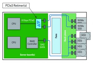
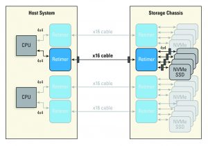
An example storage server is diagrammed in Figure 6. Because the SSD and HDD drives are accessible and replaceable from the front of the chassis, they are usually a long distance from the CPU, PCIe switch or RAID controller with which they communicate. IDT Retimers are being used to extend the signaling distance (or reach) of PCIe 3.0 from the CPU, often across 20+ inches of trace, with three different PCBs and three sets of connectors!
In the example shown, the PCIe 3.0 Retimer has been placed on the backplane PCB. This positioning of the Retimer divides the channel close to the SSD, which is good because the SSD is usually an unknown variable at the time of system design. Different brands and types of SSDs may be selected by the end user and installed during system deployment, but all SSDs will not operate exactly the same with respect to RX and TX performance. The longer channel segment between the Retimer and CPU can be optimized by the designer by adjusting trace properties for good SI results, because that segment is fully defined, known and fixed during the design. The channel segment between the Retimer and the unknown SSD, because it is shorter, will have inherently better signal margins allowing proper operation even with variable SSD signal characteristics.
Often it is not practical to place a Retimer on the backplane PCB as diagrammed in Figure 7, and instead may be placed on the mid-plane card. This results in the Retimer being positioned physically closer to the middle of the signal channel, which is good design practice and can also work well. When the Retimer is placed towards the middle of the channel, both the Retimers RX and TX equalization functions can be fully utilized.
Note in the Figure 7 example that there are both flash-SSDs and rotational-HDDs shown with the objective to convey the concept of tiered-storage. The more expensive NVMe SSDs attached directly to the CPU provide very high performance for quick access to often used information, while the HDDs provide much larger data capacity at a lower cost for seldom used or archival data and may even be arrayed for redundancy against failure and data loss.
Running very high-speed signals across long FR4 traces with multiple connectors as diagrammed previously is technically challenging, and it is also common for cables to be used to connect host controllers with the SSD (and HDDs), as diagrammed in Figure 7. Although good cables will be more expensive than a PCB they typically have lower attenuation and crosstalk and can provide better signal quality for a given distance. Within a chassis, cables of 1 meter length are not unusual and Retimers are used to assist the 8Gbps signals cross 1-cable, 3-connectors, and 3-PCB changes. Each of these material changes creates signal reflections and noise which hurts signal quality.
PCIe 3.0 cable applications
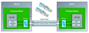
Chassis-to-chassis cabling for 8 GTps PCIe communication is another new application for PCIe 3.0 Retimers. Copper-wire cables are used to connect two system chassis or to connect a remote peripheral. Figure 8 diagrams examples, but other applications, such as using PCIe cables within a single large chassis to connect different sub-systems are also being implemented today.
Although a standard for cabling PCIe 3.0 has not yet been released by the PCI SIG many system vendors are already implementing 8 GTps PCIe 3.0 cable solutions. Solutions implementing the 12G SAS SFF-8643 (internal) and SFF-8644 (external) connectors and cable are already popular options for 8 Gbps PCIe 3.0 and may be adopted by the PCI SIG committee. In parallel, an original PCIe 3.0 cabling standard called OCulink is also under development within the SIG.
An external cable port allows cables of different lengths to be installed, and this is one scenario where the value of the PCIe 3.0 standard’s Equalization Procedure becomes obvious and essential. At the 8 GTps data rate, proper link operation is very sensitive to correctly tuning transmitter and receiver parameters. Cables of different lengths, or from different vendors, and even from different manufacturing lots will have different characteristics. Manually tuning 8 Gbps signals is a tedious and time consuming effort for a skilled engineer. It is impractical for an end user to do this manually during system deployment and with varying cable lengths. The Equalization Procedure which the PCIe 3.0 Retimer supports gives an optimal tuning for varying cable lengths and is done automatically at system power-up and invisibly to the (cable) installer. The Equalization Procedure delivers a significant risk reduction and user simplification, and is a valuable feature of the PCIe 3.0 Retimer.
Active optical cables
A variation of external cables for PCIe is to use an Active Optical Cable (AOC) instead of copper cable. Optical cable can enable much greater distances than copper cable, but is much more expensive. Today, there are no commercially available AOCs which are specifically designed to be fully compliant with the PCIe specification, so instead AOCs which were developed for Ethernet, InfiniBand or Fibre Channel are adapted for PCIe 3.0 use. AOCs of sufficient performance are commercially available from a number of vendors. Using cables that are not PCIe compliant forces system design constraints and compromises in system functionality. For example, link power management and hot-swap features are not guaranteed to work across an AOC. However, the more important question for this article is how do PCIe 3.0 Retimers relate to optical cabling?
A system design supporting AOCs will have a socket and connector bracket for attaching the cable. Typically this is of the QSPF+, CFP or similar style. When compared to passive copper cables, AOCs are quite expensive. So for shorter connections, using a passive copper cable plugged into the QSFP+ or CFP connectors is preferred. However, an 8Gbps signal crossing a large board and then transitioning onto and off the cable to another board usually allows only very short cables for reliable operation ( <=1.0m for example, with good quality cable). When a PCIe 3.0 Retimer is placed in the system adjacent to the cable connector at both cable ends, it will isolate the PCB traces from the cable wire and enable much longer passive copper cables (4.0m for example). If an AOC (with matching connector style) is installed into the same socket connecting to the Retimer, it can also work (accepting that the same constraints mentioned previously still exist). The AOC cable is then used only for connections longer than a few meters (4m to continue this example). Typically, systems will have needs for many shorter connections where less expensive copper cables can be used, and have only a few very long connections that require active optical cable. The cost savings of an interface that supports both copper and AOC can be substantial. This configuration is diagrammed in Figure 9. PCIe 3.0 over optical cable is expected to become much more common for HPC and telecom applications in the future, and even with future PCIe focused AOCs the dual-mode ability to support both passive-copper and AOC will remain important.

This paper has described a few emerging applications for PCIe 3.0 Retimers. These applications include NVMe SSD storage solutions, 8 GTps/channel cable connected systems, and dual-mode copper-optical PCIe 3.0 ports. A PCIe 3.0 specific Retimer which is compliant to the PCIe 3.0 protocol and implements the full Equalization Procedure is essential for open-slot, open-port, interoperability and compatibility. A PCIe 3.0 Retimer can solve difficult system design issues with high-speed signal integrity. The PCIe 3.0 Retimer can help insure low bit-error-rate links, high-performance and high- reliability across links that might not otherwise be possible or practical.
Ken Curt is the Princial Product Marketing Manager at Integrated Device Technology.
www.idt.com


Leave a Reply
You must be logged in to post a comment.