Electrically driven reaction wheels use conservation of angular momentum to keep a satellite pointed in the right direction, eliminating the need for fuel-powered and limited thrusters.
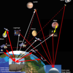
Orbiting satellites usually must maintain a precise and stable orientation for various reasons: to keep their cameras or radar pointed at their Earth targets or to keep their telescopes pointed at desired objects in space. This need for pointing accuracy and consistency applies to satellites low-Earth orbit (LEO) with orbital radii of 2,000 km/1,200 miles or less and orbital period of under two hours, to medium Earth Orbit (MEO) satellites between 2,000 km/1,200 miles and 35,700 km/22,300 miles, and even geostationary ones in a fixed position above the Earth at about 35,700 km.
In theory, once a satellite is in orbit, it should maintain that set orientation in the vacuum of space and weightless environment, but that’s not the case at all. Small yet significant ongoing rotational perturbations will occur in x-, y-, and z-directions due to solar radiation pressure on all satellites, as well as aerodynamic forces and drag acting on LEO and lower-range MEO satellites.
To correct for such changes in pointing accuracy – also called “attitude” – satellite designers can choose among several options, with one of the most common being the use of reaction wheels (Figure 1). These have a typical diameter between 15 and 30 centimeters (about 6 to 12 inches) but smaller and larger ones, depending on the size and mass of the satellite in which the reaction wheel is being used.
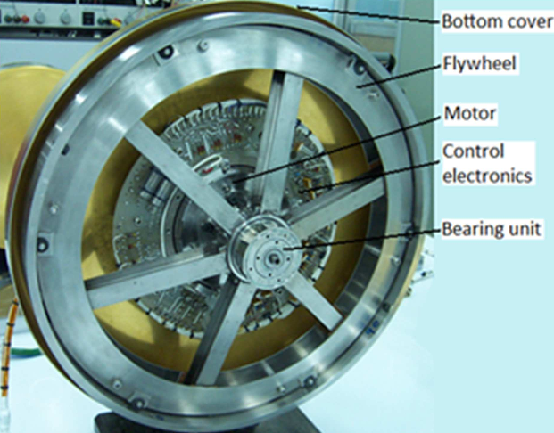
What is a reaction wheel (sometimes called a momentum wheel)? It’s a sibling of the better-known gyroscope and uses the same principles of physics but in a different way. The classic mechanical gyroscope is a rotating mass that maintains a fixed orientation despite the rotation of its gimbaled bearings around its x, y, and z axes. Therefore, it can be used to indicate changes in the system’s orientation in which it resides. The gyro maintains a constant rotational speed in nearly all applications once it is “spun up” to its rated value by an electric motor or even a gas jet.
The reaction wheel also uses a rotating mass connected to an electric motor, but the rotational speed of the mass is varied under careful control; typical nominal speed is several thousand revolutions per minute (rpm). The wheel exploits the basic law of conservation of angular momentum. When its rotation speed is changed, it causes the spacecraft to begin to counter-rotate proportionately to maintain angular momentum at a constant value. Another way to look at the conservation of angular momentum is that slowing down or speeding up the rotation will induce a momentum exchange which provides stability to the satellite.
Reaction wheels are a clever and effective use of a simple, basic physics principle. They enable control of a satellite’s angular position (attitude) without requiring positioning thrusters or any other external applicators of torque. Note that this is angular control only, as they cannot affect the linear motion of the satellite along its x, y, or x-axes.
Use of reaction wheels brings multiple benefits, beginning with a significant reduction in the payload needed for fuel for the thrusters, with no need to worry about using up that precious resource which will eventually be depleted. Since the reaction wheel is electrically powered, it can function as long the satellite can deliver power via its solar panels.
In addition, reaction wheels are extremely accurate and can enable precise repositioning. As the attitude of the satellite shifts, the reaction wheel is automatically directed to induce a counter-rotation of the spacecraft through conservation of the angular momentum.
Another important benefit compared to thrusters is that the “exhaust” from a positioning thruster can fog or cloud nearby optics. That concern does not exist with the reaction wheel.
Of course, ground controllers can also initiate reaction-wheel slow-down or speed-up to control the rotation, and electrical control is more precise and easier than thruster control. The reaction wheel also contains a torque sensor to provide closed-loop motion feedback and provide useful diagnostic information on the state of its motor and bearings.
Reaction wheel arrangement
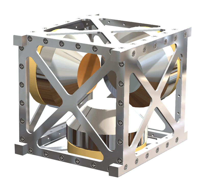
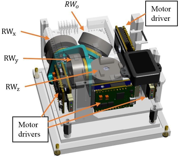
Again, reaction wheels cannot move the spacecraft or satellite from one place to another; they can only induce rotation around the wheel’s axis of rotation. Most designs use three orthogonal reaction wheels to have complete attitude control via angular rotation for the system (Figure 2).
In some cases, only two reaction wheels are used in a non-orthogonal arrangement. Managing the pair in tandem using complicated vector equations makes it possible to affect rotation around the three axes. Still, control is more complicated, and there is no possibility of redundancy or backup.
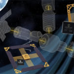
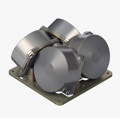
Some designs, in fact, use four reaction wheels in a tetrahedral (pyramid) arrangement, so three-axis control is possible even if one wheel fails (Figure 3). Note that there is no need for a redundant wheel for each axis, and that is a major advantage.
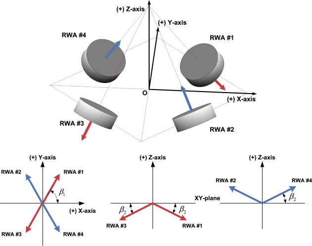
The three active gyros are not orthogonal, so their performance is linked, but again, full control is possible with the appropriate mathematical transformation of vectors, Figure 4.
Sometimes, the “spare” wheel is mounted at a non-orthogonal angle with respect to the three primary wheels are orthogonal, Figure 5. In these cases, “normal” operation is mathematically simplified while using the spare wheel adds to numerical complexity but is entirely feasible.
Not surprisingly, rotor bearings are a common source of failure. If they are lubricated for long life, the entire must be in a hermetically enclosed assembly to prevent lubricant molecules which otherwise outgas in the vacuum of space from containing the system. This adds weight and design/fabrication complexity as the wire-feedthroughs must also be sealed. Some designs use magnetically levitated bearings to avoid ball bearings and lubrication, but these also have issues.
Part 2 looks at additional issues related to the use and construction of reaction wheels.
Related EE World Content
How to make the most of low-cost satellites for remote IoT apps
Enhanced GNSS constellation simulator helps field satellite navigation system
Smaller, cheaper, better: Microsatellites
Challenges in designing electronics for satellites
Gyroscopes, Part 1: Context and mechanical designs
Now that’s a test instrument: Inside the Webb space telescope
External References
- University of Toronto Space Flight Laboratory, “Enabling Reaction Wheel Technology for High
Performance Nanosatellite Attitude Control” - Charles’ Labs, “Reaction Wheel Attitude Control”
- Universe Today, “Spacecraft Gyroscopes And Reaction Wheels. You Can Never Have Enough”
- Space News, “Kepler Space Telescope Reaction Wheel Remains a Concern”
- Futek Advanced Sensor Technology, “Torque Sensor – Satellite Reaction Wheel Torque”
- Science Direct, “Micro-vibration model and parameter estimation method of a reaction wheel assembly”
- Honeywell Aerospace, “Small Satellite Class Reaction Wheel Assembly (RWA) HC7 AND HC9”
- Honeywell Aerospace, “Small Satellite Class Reaction Wheel Assembly (RWA) HRO4”
- Astrobytes, “Kepler Reaction Wheel Failure Cripples Spacecraft, but Mission Thrives”
- Tech Briefs, “Ultra-High-Speed Magnetically Levitated Reaction Wheels for Small Satellites”
- Utah State University, “Design and Testing of a Nanosatellite Simulator Reaction Wheel Attitude Control System”
- Wikipedia, “Reaction Wheel”
- Science Direct, “Optimal uses of reaction wheels in the pyramid configuration using a new minimum infinity-norm solution”