We now take as a “given” the ability to know where we are and where we are going, and do both with accuracy and precision (and with simplicity and low cost, but these are relatively recent developments. Prior to the availability of inertial measurement systems based on gyroscopes and accelerometers, navigation was a time-consuming, difficult, and rough process done with compass, sextant, and radio-based systems such as LORAN.
Even though LORAN was a tremendous improvement over the compass and sextant, accuracy was modest at best (a few miles, under ideal conditions), coverage was uneven, and it required considerable skill to use. In contrast, today’s inertial measurement units (IMUs) can locate, navigate and guide with incredible precision, and it all starts with the spinning-rotor gyroscope.
This FAQ will review the basics of the traditional IMU (Part 1), and then look at how the laser-based and MEMS-based gyros have largely made the spinning-rotor IMU obsolete (Part 2)
Q: What is an IMU?
A: An IMU consists of a gyroscope-based inertial platform along with a trio of orthogonal accelerometers. Three orthogonal rotating-mass gyros, Figure 1, are mounted in a three-axis gimbaled platform and maintain a fixed attitude (orientation) in space, while the accelerometers on the platform continuously provide signals for x, y, and z acceleration with respect to that fixed platform. At the same time, orthogonal rotary-angle sensors called resolvers report on the orientation of this fixed-in-space platform with respect to the vehicle in which it is riding, Figure 2. (In practice, some designs use torque motors instead of resolvers, and the force they require to restore the platform from its displaced position back to its initial position provides the angular information.)
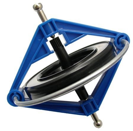
Fig 1: A classic child’s toy gyroscope, but in a significantly improved implementation, is the heart of an inertial measurement unit. (Image source: Pinterest)
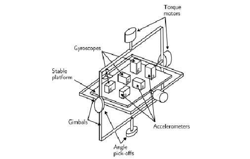
Fig 2: A complete rotating-mass IMU uses a trio of orthogonal gyroscopes to establish and maintain a fixed platform orientation in space, and also has three orthogonal accelerometers; it requires no tangible “access” to the outside to determine position. (Image source: Researchgate)
As the name states, the gyro-based system is “inertial” which means it requires no external inputs at all: solar, stars, magnetic, radio waves, nothing. It is based in the basic principles of physics: a rotating mass (here, the gyro) resists changes in orientation, while a mass which is accelerating feels a force. As such, an IMU is absolutely immune to external conditions or interference, and is a true “black box,” totally closed system.
Q: Why do we even need this? After all, we have GPS, which is accurate, cheap, and easy to use.
A: GPS is just that: a global system. It does not work beyond the orbit of its constellation of satellite’s around the Earth, nor does it work underground or in tunnels, where signals are too weak. Further, it is at the mercy of spoofing, interference, and other limitations.
Q: How does the acceleration information combine to make the IMU work?
A: From basic physics, the integration of the three accelerometer output signals (originally done with analog circuitry and op amps and now done digitally) provides velocity vectors; by integrating each of the three again, it reveals distance traveled (displacement). Recall from Newton’s laws that velocity is the derivative of distance or displacement with respect to time; while acceleration is the time derivative of velocity. Therefore, by knowing orientation (and thus direction of travel) as well as displacement, position in space can determined in real time.
Q: Brief background, please: what’s the “who, what, and where” about gyro-based IMUs?
A: Gyros have been used a children’s toys a few hundred years, but the first serious efforts to use gyros for aircraft guidance began in the 1920s, and they were even used for coarse navigation by WW2 (the German V-2 rockets had them). Much for the critical work and inspiration was done in the US by Dr. Charles Stark Draper of MIT, who drove the development from theory, to understanding of error sources, design, and final implementation. Among their other accomplishments, Draper and his team designed and built the IMUs which guided Apollo spacecraft to the moon, as well as many of the missions which have explored our solar system.
Q: How is the accelerometer portion of the IMU implemented?
A: Although there are several ways to do this, the most accurate way, ironically, requires using another gyroscope—but not in a gimbaled-platform arrangement. Instead, it is used in what is called a PIGA—a pendulous integrating gyroscope accelerometer, Figure 3 (how a PIGA works to indicate linear acceleration is a topic for another time).
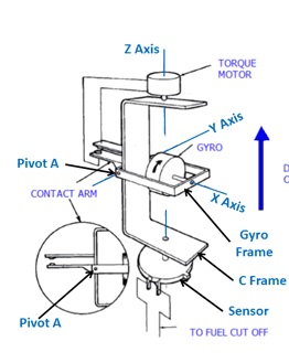
Fig 3: A traditional high-end accelerometer also uses a gyroscope, but suspended as a pendulous mass which reacts to linear acceleration along one axis. (Image source: Woodbank Communications Ltd)
Q: What is the size of a high-performance spinning rotor-based IMU? What are its drawbacks, despite the excellent performance?
A: There are usually enclosed in a spherical housing, ranging from the size of a large grapefruit to the size of a soccer ball. An accurate spinning rotor gyro requires the ultimate in mechanical design, as any imperfection will affect accuracy and cause errors such as drift over time and temperature. Everything must be as “perfect” as possible: the balance of the rotor, the bearings on which it spins, the frictionless gimballed platform for which it maintains a fixed orientation in space, the sensors which read the platform orientation with respect to the enclosure, and more. Even a tiny imperfection will lead to an accumulation of errors which build up over time and distance, which is unacceptable for most navigation and guidance challenges where the mission involves long distance, long periods of time, or both.
Q: Is the spinning-rotor gyro-based approach now obsolete?
A: Yes and no. For the vast majority of applications, newer technologies based either on lasers or MEMS devices are available with very, very good performance, and have largely made the mechanical gyro and its IMU obsolete. These alternatives have lower cost, are far less complicated mechanically, more reliable, and use far less power. They can also be smaller (for the MEMS units).
However, the spinning-rotor gyro unit is still needed for the ultimate in IMU performance (although perhaps not for much longer). It is used on intercontinental missiles which must reach targets thousands of miles away with mile-or-better accuracy, and submarines which must remain submerged and “cloaked” for weeks and months. Such a top-end gyro is the ultimate in electromechanical design, where every source of error or inaccuracy has been identified, modeled, and reduced by exquisite design and execution. For example, the gyro bearings use pressurized gas rather than ball bearings; and some gyros even “float” the assembly in a high-density, non-conducting silicon liquid to make the gyro buoyant and so reduce the effects of gravity.
Q: What is the ultimate in spinning-rotor designs?
A: Among the highest-performance systems ever devised and built is used in the Gravity-Probe B satellite, used as part of the program to search for “frame-dragging” of the space-time continuum due to the relativistic distortion effects of mass on gravity, and which is related to gravity waves. This gyro uses a set of incredibly near-perfect spheres for rotors, each “spun up” without physical contact using bursts of gas; the unit’s orientation is sensed by a non-contact scheme similar to eddy currents.
Q: What are the alternatives to IMUs using a spinning-rotor gyro?
A: There are two very different alternatives: the laser/optical fiber design, and the MEMS implementation. These will be discussed in Part 2.
References
- “Are We There Yet? Innovations That Led to Navigational Certainty”
- “Fiber-Optic Gyro Merges Optical Interference, Relativity to Define Motion and Location”
- “Spinning spheres test relativity’s subtlety” (Gravity-Probe B)
- Donald MacKenzie, “Inventing Accuracy: A Historical Sociology of Nuclear Missile Guidance,” MIT Press, 1990, ISBN: 9780262132589.
- Anthony Lawrence, “Modern Inertial Technology,” Springer, Second Edition, 1993, ISBN: 0-387-98507-7.
- “PIGA Accelerometer“
- https://www.draper.com/history
- “Introduction to MEMS gyroscopes”
- “A Survey on Ring Laser Gyroscope Technology”
- “MEMS Gyroscopes”

Leave a Reply
You must be logged in to post a comment.