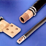
Electrical power moves through a conductor when opposing dc or ac voltages are applied at opposite ends. Charge carriers — free electrons or electron holes in semiconductors, ions in electrolytes – migrate toward the opposite poles. Metals, with abundant free electrons, have high conductivity. All conductors are partial insulators and all insulators are, to some theoretical degree, conductors.
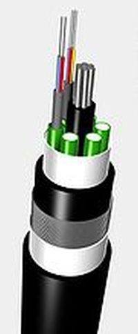
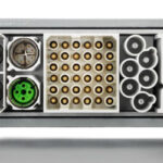
Multimode optical fiber
Optical fiber, which is a specialized waveguide, conveys light energy. Unlike electrical conductors, it does not convey charge carriers, but rather light waves that bounce from side to side inside a tubular waveguide. In optical fiber, there is no impedance in the sense of capacitive or inductive reactance. Thus optical waveguides don’t have an intrinsic impedance as to cables and RF waveguides.
An interesting difference between electrical conductance and optical waveguide transmission is that an electrical circuit ordinarily requires a hot wire and return conductor. In contrast, optical fiber like other waveguides conveys power through a single pathway.
However, in both modes, there is attenuation, which places limits on how far power and information can transmit. Attenuation in optical fiber arises from atomic absorption, scattering due to impurities, flaws in the medium and reflections from splices and connectors.
Because of differing electron orbital configurations, atoms in various materials absorb specific wavelengths of high-frequency electromagnetic energy in different amounts. As light passes through optical fiber, its observed color changes with distance. Accordingly, if you look into the edge of ordinary window glass, it appears green. That is because other colors are absorbed to a greater degree by clear glass, and this effect is a function of the distance that the light travels.
Scattering by impurities and flaws in the medium is known as Rayleigh Scattering. The degree to which this phenomenon arises varies with the light wavelength and the particles that scatter it. A longer wavelength and smaller particle results in less scattering. Shorter wavelengths and large particles mean more scattering. Because any optical fiber core contains particles and because light wavelengths are relatively short, there is always a finite amount of scattering and measurable attenuation.
Splices and connectors are a necessary and inevitable part of any fiber network. It is not possible to create a perfect impedance match, and for that reason there will always be some reflections. They are the cause of data collisions. The reflections never leave the fiber, instead contributing to attenuation in the link between transmitter and receiver.
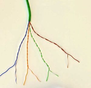
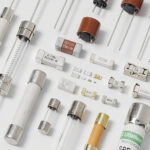
Cat 5e UTP electrical data cable.
Attenuation in electrical conductors is primarily from impedance, a generic term that includes resistance, capacitive reactance and inductive reactance. Resistance diminishes electrical conductance irrespective of the frequency, except in some specialized phenomena such as the skin effect. Capacitive and inductive reactance are frequency dependent. All electrical conductors exhibit some degree of resistance, capacitive reactance and inductive reactance regardless of frequency. But capacitive reactance is greatest at low frequencies and falls off as frequency rises. Inductive reactance is greatest at high frequencies and least at low frequencies.
Impedance is a complex number. It has both magnitude and phase, as opposed to resistance, which possesses only magnitude. The reciprocal of impedance is admittance, measured in siemens.
Oliver Heaviside investigated and described impedance in 1886, shortly after he studied the skin effect and patented coaxial cable. He demonstrated that uniform inductance in a long telegraph line would diminish distortion and attenuation.
Impedance is measured in ohms and conforms to Ohm’s law for any given frequency. Voltage division, current division, Thévenin’s theorem and Norton’s theorem are applicable to AC circuits when impedance replaces resistance.
Capacitive reactance is defined by:
XC = 1/2πfC
Where XC = capacitive reactance in ohms
f = frequency in hertz
C = capacitance in farads
Inductive reactance is defined by this equation:
XL = 2πfL
Where XL = inductive reactance in ohms
f = frequency in hertz
L = inductance in henries
In data cables, attenuation equates to signal loss. This may be quantified as the ratio of signal power at the input to signal power at the output. It is expressed as decibels per foot (dB/ft). A cable exhibits different amounts of attenuation at different frequencies, typically greater attenuation at higher frequencies. This is because capacitive reactance, which is less at high frequencies, tends to shunt out the signal since unintended capacitance is generally a parallel phenomenon. Conversely, inductive reactance is greater at higher frequencies. It attenuates the signal to a greater degree at high frequencies since unintended inductance is generally a series phenomenon, occurring in the two conductors in a serial bus.
Another source of attenuation, which is also greater in longer runs, is the cumulative effect of interference from other networks or nearby nonlinear loads. In a wireless system, physical obstructions cause attenuation. Reduction of attenuation can be achieved by higher twist rate in UTP (unshielded twisted pair) cable and maintaining signal power by means of repeaters.
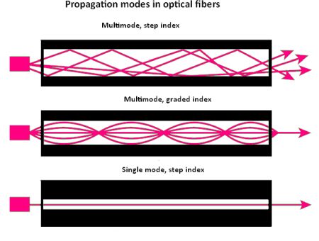
Light can pass through fiber optic media as a single-mode or multi-mode, Within multimode fiber, the degree of refraction change between the core and the cladding is more gradual for graded index fibers.
Multimode optical fiber is used in relatively short runs, typically inside a single building. Single mode, with repeaters at wide intervals, is used by utilities in much longer often underground runs in conduit. The most obvious difference between them is that multimode fiber has a much larger core.
The signal source for multimode fiber is typically an LED. Single-mode fiber typically uses a laser. Light from an LED is not coherent. It consists of a mix of frequencies that are not in phase. Consequently, the differing wavelengths strike and bounce off the core-cladding interface at disparate angles, resulting in signal dispersion.
The laser light source for single-mode optical fiber is coherent, consisting of a single wavelength, which follows more closely the inevitable bends and curves in the waveguide, with minimal dispersion. The signals travel farther between repeaters, and there is far less attenuation and greater bandwidth.
In both modes, attenuation comes from optical fiber irregularities including impurities in the core, and variation in diameter and cross-sectional profile. Cable splices and connectors limit bandwidth, and insufficient light from the source results in modulated light that lacks sufficient power at the destination to be demodulated accurately.
Dispersion degrades a signal cumulatively over distance. It consists of chromatic dispersion and modal dispersion. Chromatic dispersion is a consequence of variations in the speed of different frequencies of the light as it travels through a solid core. Modal dispersion, which compromises multimode fiber as opposed to single mode, limits the maximum bit rate. Thus, chromatic dispersion creates greater attenuation over longer distances.
Attenuation is sometimes intentionally introduced into a fiber link when the signal is too strong or to reduce birefringence. The usual means by inserting a commercially available attenuator into the signal path. An attenuator is a passive optical component that intentionally reduces the optical power propagating in a fiber optic cable.
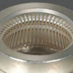
As an experiment, you can increase the attenuation in an optical link by introducing a moderately sharp bend in the cable. As the angle of internal reflection becomes more severe, the signal amplitude drops, at first gradually and then abruptly. This bend can be made without kinking and permanently damaging the medium by wrapping it gently about a round object and temporarily securing it with electrical tape. The results can be monitored in an oscilloscope using an optical probe.
Intentional attenuation may be introduced when the data rate (frequency) is high enough by moving your hand close to the conductor on the outside of the insulation. In this way, you can become a parasitic antenna element. The coupling is capacitive, and it is lessened when the conductors have been intentionally twisted.

Leave a Reply
You must be logged in to post a comment.