The CAN (controller area network) protocol was developed by the European automotive electronics company Robert Bosch GmbH in 1983 for in-vehicle networks. The intention behind the development of the CAN protocol was to enable robust data communication between different electronic control units (ECU) and microcontroller control units (MCU) of a vehicle on a single wire to get rid of complex peer-to-peer wiring between them — despite communicating data over a single bus, CAN does not require any host computer.
The standard CAN protocol operates at the OSI model’s physical and data link layers. The other protocol stack layers are not implemented within CAN, which proved to be a great advantage. System engineers are free to design other protocol stack layers in a way that best suits an application. Today, CAN makes variations like CANopen, DeviceNet, and J1939, allowing implementation of all seven protocol stack layers (along with standard CAN layers 1 and 2 for specific use cases); CAN has a reputation as a robust, simple, cross-domain, versatile serial network communication protocol that must be implemented whenever frequent real-time data communication is required between electronic devices belonging to different domains. So, learning the implementation of standard CAN protocol seems beneficial.
In this article, we will take a look at the CAN protocol and its distinct features. Then, we will explore some typical applications of CAN protocol and investigate how CAN is utilized there.
CAN standard
CAN specifications define the CAN protocol and the CAN physical layer. The protocol is mainly defined by ISO-11898 specifications, but other specifications like ISO-11519 for low-speed serial data communication also apply to the protocol. The ISO-11898 specification is divided into three parts: the first part defines the specifications for the data link layer and single physical link, the second part defines the CAN physical layer for high-speed CAN, and the third part defines the CAN physical layer for low-speed CAN.
The low-speed CAN has data rates of 5 Kbps, 10, 20, 50, and 125 Kbps. The high-speed CAN has data rates of 250, 500, 800 Kbps, and 1 Mbps. In a CAN network, the data is communicated over a shielded or unshielded twisted pair or ribbon cable having a characteristic impedance of 120 ohm. The DB9 (male) connectors are used as per CiA DS-102 specification. CiA stands for “CAN in Automation.” The maximum range of a CAN bus is 1000m (at 40 Kbps). For high-speed CAN, the maximum range is 40 m at 1 Mbps. A maximum of 127 nodes can be connected to a CAN bus.
How CAN protocol works
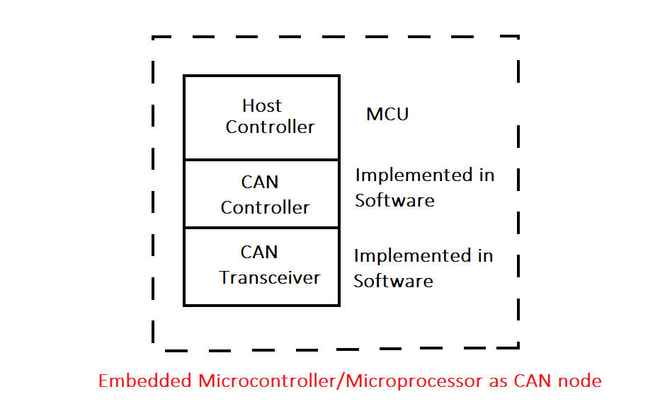
In a CAN network, each electronic device or system connected to the bus is a node. Each node consists of three elements: host controller, CAN controller, and CAN transceiver. The host controller is a microcontroller or processor within the device/system that runs some application for a specific job. The CAN controller handles the transmission and reception of CAN messages between the host controller and the CAN bus; it acts as a protocol handler. The CAN transceiver takes care of the transmission and reception of CAN messages over the CAN bus. It acts as a line driver. While the host controller is a physical controller/processor, the CAN controller and CAN transceiver are implemented in software or firmware.
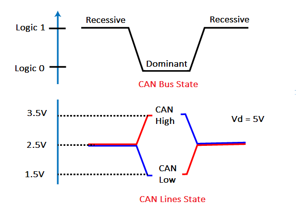
Each node is a CAN transceiver. The data is communicated in a half-duplex, asynchronous manner. The bits are transmitted over the CAN bus using differential voltage. The two wires in the CAN bus are called CAN low and CAN high. There are two unusual logic states of the CAN bus called recessive and dominant. Logic 1 is the recessive state, and logic 0 is the dominant state. Usually, the bus rests at a recessive state, i.e., logic 1. For recessive state or communicating logic 1, both wires CAN low and CAN high are applied a voltage half of supply voltage VDD or VCC. The supply voltage is typically 5 V, so both wires are applied at 2.5 V. As a result, the differential voltage between the wires is 0 V. This is read as logic 1. In the dominant state, CAN high is pulled up to 3.5 V, and CAN low is pulled to 1.5 V. So, the differential voltage between two wires is 2 V. This is the dominant state of the bus, which is read as logical 0 by the CAN transceiver.
The dominant state always overrides the recessive state. The bus only rests at the recessive level when all nodes send the recessive bit. Due to AND logic, even if a single node sends a dominant bit, the bus state is dominant.
CAN is a message-based protocol. The data is communicated in the form of message frames. A frame is a meaningful sequence of bits. There are four types of message frames – data frames, remote frames, error frames, and overload frames. Data frames carry messages from a CAN transceiver, remote frames are sent to request data from other CAN transceivers, error frames are sent to indicate an error in a data frame, and overload frame is sent to indicate overloading of data frames — indicating the requirement of delay in transmission of data frames. An identifier field identifies each frame. The identifier field is 11-bit long in standard CAN and 29-bit long in extended CAN protocol (to learn more about the structure/format of the data frames and other CAN frames, check out this article on standard CAN protocol).
At a time, only one node can access the bus. The access method used in the CAN protocol is a carrier sense multiple access with collision detection (CSMA/CD) method called bitwise arbitration (BA). The identifier field of a data frame sets the priority of the message. The lower the identifier value, the higher the priority. So a data frame with identifier field 0x6C3 has higher priority than a data frame with identifier field 0x7B4. Similarly, a data frame with identifier field 0x7B3 has higher priority than a data frame with identifier field 0x7B4.
Any node can access the CAN bus if it is idle, i.e., in a recessive state. If two or more nodes try to access the bus simultaneously, the node transmitting a data frame with a lower identifier field i.e., a data frame with higher priority gets the bus access. The identifier fields are compared bit-by-bit from MSB (bit 10) to LSB (bit 0) until a node wins arbitration. If a node is transmitting a correspondingly recessive bit while any other node is transmitting a dominant bit, the node losses the arbitration. In this manner, the node transmitting a data frame with the lowest identifier value i.e., highest priority gets access to the CAN bus. The other nodes have to wait for their turn according to the priority level of their data frame.
A data frame transmitted by a CAN node is transmitted to all other nodes on the bus; it is filtered by them and received only if the identifier field applies to them.
Why CAN?
There are many reasons to choose the CAN protocol. CAN is a serial network communication protocol and requires only two wires to communicate data among multiple devices. All the devices connected in a CAN network communicate over a common two-wire bus. No two nodes/devices need to be connected one to one.
As the CAN controller, as well as CAN transceiver, are implemented at the software/firmware level, and the protocol is implemented at only the physical and data link layer, allowing devices from different domains to communicate on the same bus. The other layers of the OSI model on each device or node can be individually designed by system engineers as per the need or role of the particular node/device.
CAN is a message-based protocol. Unlike address-based protocol, this type of protocol is not affected by adding or removing nodes on the bus. The messages transmitted over the bus are broadcast to all other nodes and filtered according to the identifier field at the node level. The priority is attached to the message frames, not the CAN nodes by means of their identifier fields. In this way, there is no need to identify nodes sharing the CAN bus. The nodes can be inserted or deleted without affecting the CAN network.
As built for in-vehicle networks, the protocol uses differential voltages. So, data cannot be corrupted or altered by other nodes. Due to differential voltage levels, CAN is one of the most robust serial communication protocols.
CAN bus has the least chance of any collision between devices. As mentioned, by bitwise arbitration the priority is attached to messages, so the most important messages are communicated first over the bus, irrespective of the nodes transmitting them. The data is transmitted over the bus asynchronously and prioritized by bitwise arbitration.
The protocol enables error checking for reliability and offers excellent noise immunity. CAN is a widely used serial communication protocol for low-speed but frequent data exchange among embedded electronic devices. Many chips have built-in CAN interfaces. The semiconductor chips for setting up the CAN network are available from vendors like Maxim Integrated, Texas Instruments, Analog Devices, Microchip Technology, NXP, ST Microelectronics, and others.
Applications of CAN
CAN protocol is widely used by all types of motor industry applications including passenger, heavy goods, utility, and agricultural vehicles. Though being such a robust, reliable, and versatile serial communication protocol, CAN is not just limited to automobiles. The protocol is used by the control modules of high-speed trains and aircraft, in entertainment and infotainment systems in automobiles, in the controlling and monitoring of cranes and drilling probes, within elevators and lift control systems, for building automation like heating and air-conditioning systems, in automatic doors and curtain openers, and in automated watering for glasshouses and farms, as well as having been widely adopted in medical instrumentation. Additionally, the protocol is used by sensor networks where signal robustness due to environmental factors is required. Essentially, many machine tool control systems use the CAN network as an in-device bus system enabling factory automation.
CAN in automobiles
Built for in-car networks, CAN protocol is used in most passenger cars. It enables data communication among several ECUs without any one-to-one wiring. Most cars have a CAN-based engine management system. Not just that, most cars connect body electronics ECUs all through CAN-based multiplex systems. The in-vehicle entertainment systems are connected through the CAN bus. Apart from that, CAN bus is used by in-vehicle diagnostic systems. ISO-15765 is a specification for CAN-based diagnostic interfaces. The CAN is also used for connection-oriented data communication between in-car entertainment devices.
In electric cars and hybrid vehicles, the CAN network has an unexpectedly wider role to play. It is useful for communication between inverters, battery management systems, and servo motor controllers. It also connects servo controllers with human machine interface for the driver. Though CANopen is the CAN variant that is mostly used in non-automotive applications, it is the one that is finding utility in hybrid and electric vehicles.
Many agriculture machines like excavators and forklifts rely on CAN-based networks. In truck-based cranes, the CAN is used for monitoring and control of the crane system.
CAN in public transport systems
CAN protocol is widely used in high-speed trains and aircraft. Trains use CAN to connect brake control systems. In high-speed trains, CAN is used to enable automatic braking. Trains also use CAN to communicate with sub-systems like brake control, door control, diagnostics, freight car monitoring, and to communicate with gateways at train bus systems. CAN is also useful in automating customer services and passenger information systems.
In road transport, CAN-based sensor networks are used for speed detection, traffic surveillance, and management of traffic lights. CAN is the protocol used by maritime electronic equipment as well. It is also used to connect aircraft engine control systems with flight state sensors and navigation systems.
CAN for industrial automation
Being a reliable serial communication protocol equipped with error detection methods, robust signal logic, and capability of fault confinement, CAN-based protocols like CANopen, DeviceNet, and Smart Distributed Systems are widely used for industrial machine control. Semiconductor manufacturing equipment, carton packaging machines, textile processing machines, printing machines, and quality control equipment all rely on embedded CAN networks. CAN-based distributed control systems are widely used for robot control and assembly line automation.
CAN in building automation
In building automation, the CAN protocol is widely used by sub-networks. The elevator and lift control system, air conditioning systems, automatic doors, automatic curtain openers, window shade control systems, heating and cooling systems, and lighting control systems use CAN-based protocols for communication among electronic devices from different domains.
CAN in medical electronics
Due to robust signals, error-detection capability, and cross-domain communication, CAN is a protocol widely applied for in-device communication in medical electronic equipment like X-ray machines and CT scanners. The CAN-based protocols are also applied for inter-device networking in intensive care units and operating theatres.
CAN in embedded electronics
CAN enables flexible embedded networking and is employed as a system bus in many consumer appliances and devices like washing machines, vending machines, audio video systems, coffee machines, and many other domestic appliances.