Resistance is one of the most basic concepts in electricity and electronics. And resistors are simple-looking devices. Given their apparent simplicity, the range of resistor types and their capabilities can be surprising.
This FAQ looks at some common resistor types and tradeoffs between stability, precision, size, power handling, and so on. It briefly considers mounting considerations for resistors used in multi-GHz circuits and looks at resistors that are environmentally responsive and self-adjusting.
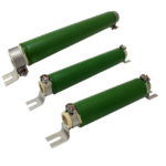
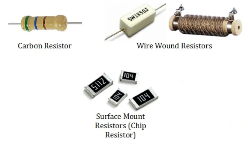
The most common resistor technologies are wire wound, carbon, and various film (chip) devices (Figure 1). Precision wire wound resistors offer several performance capabilities:
- Resistance tolerances of 0.005% can be achieved
- Stability over time is excellent, typically 15 to 50 parts per million (ppm)/year
- Temperature coefficient of resistance (TCR) is low, typically less than 10 ppm/°C, and can be controlled with the proper material selection.
- They can be fabricated with built-in fusible sections, creating fusible resistors for use in safety-critical applications
Carbon composition resistors are an alternative to wire wounds in some applications with high surge loads. They are non-inductive, and their design results in uniform distribution of surge energy throughout the resistor, reducing thermal stresses. Composition resistors are generally suitable for automatic insertion and are designed to resist disconnection under stress.
Composition resistors are used to represent the majority of the resistor market, but they are being replaced by film resistors. Composition resistors generally have poor performance, but they used to be inexpensive:
- They are generally not accurate, 1% tolerance at best, but 5% or greater is more common
- They have TCRs of 1,000 ppm/°C
- They can generate electrical noise
- Their resistance can change when subjected to over voltage stress
- If used in a humid environment, the internal moisture content can increase, and soldering or other heating can change their resistance.
As a result of these performance problems, carbon composition resistors, which used to be the least expensive alternative, have lost significant market share, and are now relatively expensive. They are available in resistance values from fractions of an ohm to 22 megohms or more and are still used in power converters, welding controllers, and similar applications, where the resistance value and stability are not critical, but where tolerance to surge energy is important.
Thick and thin films
Today, in most low power applications, thick- and thin-film chip resistors dominate. Thick-film resistors are fabricated by silk-screening a conductive ink onto an insulating substrate and firing the assembly. Thick-film have similar properties to carbon composite resistors. They are inexpensive and can be quite small. However, typical resistance tolerances are >0.1%, TCRs of 50 to 100 ppm/°C are common, and stability can be an issue, with 500 to 1000 ppm/year variations. A common application of thick-film resistor technology is in hybrid circuits where the resistors can be printed directly on the substrate, reducing the solution size and eliminating the need for soldering.
Metal thin-film resistors are a better technology. They are made by an evaporation/deposition process where a base metal is vaporized in a vacuum and deposited on an insulating substrate. They offer performance between precision wire wounds and thick-film parts with typical resistance tolerances are >0.01%, TCRs of 20 to 200 ppm/°C, and stability of 200 to 600 ppm/year.
As with the other resistor technologies, thick- and thin-film resistors offer unique sets of cost/performance tradeoffs (Table 1). Metal film chip resistors are low-cost in high quantities and have excellent frequency response with low inductance. They are suited for applications that involve MHz operating frequencies and μs rise times.

MELF resistors
When metal film chip resistors don’t offer sufficient performance, more expensive metal electrode leadless face (MELF) resistors can be used. MELF resistors are superior to metal film chips in terms of reliability, long-term stability, moisture resistance, and pulse load capability. Their cylindrical shape results in higher power ratings, and they can be operated at up to +175 °C making them suitable for use in rugged automotive and industrial environments.
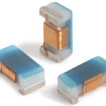
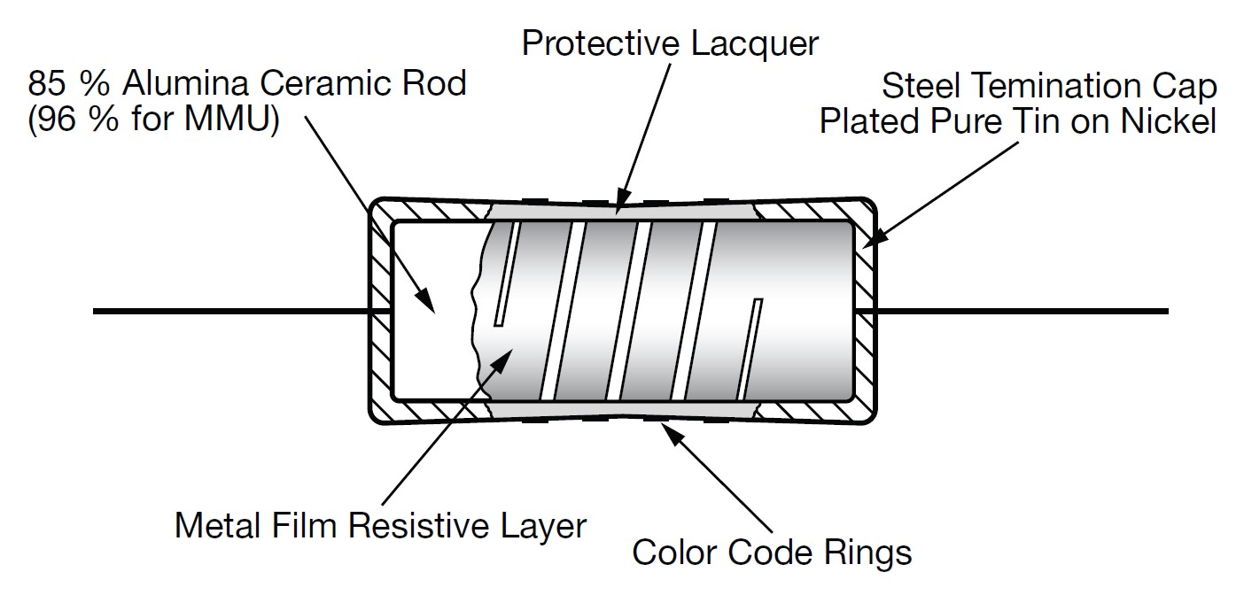
MELF resistors are fabricated using a homogeneous metal alloy film that is deposited on a high-quality ceramic body with nickel-plated steel termination caps pressed on the ends (Figure 2). The resistance value is set using a laser that cuts a helical groove in the resistive layer. A protective coating is added for mechanical, electrical, and environmental protection.
High frequency chip resistor mounting
Chip resistors can be mounted face-up or face-down. Face-up mounting has the resistor mounted, so the resistance element is on top of the resistor. Face-down mounting has the resistance element on the bottom facing the substrate. For high-frequency operation, face-down is superior in almost every respect, including reduced current loop area, lower equivalent series inductance (ESL) which results in better stability, lower noise, and improved frequency response (Figure 3). Face-down mounting also improves power handling and reduces insertion losses in multi-GHz applications.

Self-adjusting resistors
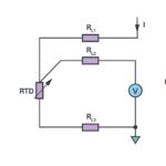
Some resistors respond to environmental factors and are self-adjusting. Their resistance changes as a result of fluctuations in temperature (thermistors), voltage (varistors) or light (photo resistors) (Figure 4). Thermistors are available in two types; positive temperature coefficient (PTC) devices that have higher resistance at higher temperatures and negative temperature coefficient devices (NTCs) that have lower resistance at higher temperatures. PTCs are often used to replace fuses and provide resettable circuit protection. In addition, PTCs are used as heaters in automotive applications. Exemplary applications for NTCs include temperature monitoring and inrush current limiting in switch-mode power converters.

The resistance of varistors (also called voltage-dependent resistors, or VDRs) varies with the applied voltage. Varistors have a non-linear current-voltage characteristic. At low voltage, a varistor has a high electrical resistance. The resistance decreases as the voltage rises. The metal-oxide varistor (MOV) is the most common varistor type. MOVs are often used in surge suppressors to protect against excessive transient voltages from lightning, power switching, and other events.
The resistance of a photoresistor (also called a light-dependent resistor, or LDR), decreases as the light level on the surface of the device increases. Some photoresistors are optimized for sensitivity to specific bands of light. Photoresistors are used for a wide range of applications such as camera light meters, controlling nightlights or street lights, and in laser-based security systems to monitor for changes in light intensity when the beam from a laser is disrupted.
Summary
Conceptually, resistors are simple components. However, when realized in a physical embodiment, resistors are not as simple as they at first appear. Performance capabilities and limitations are important factors when selecting and using resistors in practical applications. Overall, wire-wound resistors appear to have the best performance, but far more thick-film resistors are used due to their combination of good performance, small size and low cost. Thick film resistors are well suited for use in hybrid microcircuits. And there are several forms of resistors that don’t obey Ohm’s Law and experience changes in resistance when exposed to temperature, voltage, or light.
References
Carbon & Ceramic Composition Resistors, Ohmite
MELF Resistors – The World’s Most Reliable and Predictable, High-Performing Film Resistors, Vishay
Passive SMT Mounting Techniques: Face-up vs Facedown and Performance Trade-offs, IMS
Types of Resistor: Classification, Application, and Finally Clarification, Linquip
What Are Carbon Composition Resistors?, ES Components
Wirewound vs. Film Resistors, Riedon