A clock generator generally consists of a resonant circuit and an amplifier. Resonance occurs in an electrical circuit when XL = XC. At this juncture, the imaginary component of the transfer function is zero. A resonant circuit oscillates at a specific frequency. Like certain other electrical phenomena, it is capable of generating higher voltages or currents than are present at the input.
Due to small amounts of resistance in the resonant circuit, the oscillations steadily fade unless sustained by an amplifier. The mechanical pendulum is another variety of harmonic oscillator, and it too must be wound up periodically to prevent damping.
In addition to resonance, there is also the phenomenon of antiresonance. It is characterized by a distinct minimum amplitude of the waveform in an oscillator when operated at the antiresonant frequency.

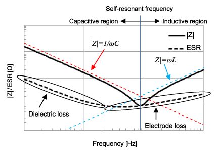
A Z vs frequency graph for a Murata capacitor. The transition area from capacitive to indutive impedance is clear.
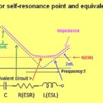
It is interesting to examine how antiresonance can arise. First recall that the impedance of a stand-alone capacitor drops with increasing frequency according to the familiar relationship XC=-1/(2πfC). In real life, capacitors only behave this way up to their self-resonant frequency. At higher frequencies, the capacitor’s parasitic inductance dominates its behavior. The effect arises from the fact that real capacitors have an equivalent circuit consisting of a capacitor in series with an inductance–arising from leads, electrodes, and so forth–and a series resistance (ESR) primarily caused by losses in dielectrics. Capacitor models also sometimes contain an insulation resistance (IR) term in parallel with the capacitance that corresponds to the dielectric resistance to leakage current.
A point to note is that between the regions of capacitive and inductive behavior, the impedance of the device is only limited by the parasitic series resistance.

The resulting impedance curve of two parallel capacitors where there is overlap between capacitive and inductive regions, causing an antiresonance. YouTuber FesZ Electronics delved into this case in some detail.
Now consider the case where two capacitors are wired in parallel and they differ in the value of their capacitances. Of course, when two ideal capacitors are in parallel their capacitances add. For frequencies where both of the two devices behave like capacitors, the sum of the two capacitances have a lower impedance than each of the two on their own. Ditto for the region where both capacitors behave like inductors. But suppose each of the two capacitors transition to inductance at different frequency ranges. The result can be an overall impedance that is far worse than that of either capacitor separately. This is the region of antiresonance. Put another way, where the impedance graphs of the two devices meet, we effectively have an inductor in parallel with a capacitor–basically a resonant LC circuit having its own resonant frequency.
By extension, adding more capacitors in parallel can make the problem worse. For every added capacitor, there is an additional peak in the overall impedance at a frequency that depends on the individual characteristics of the additional capacitor.
The antiresonance region can cause a variety of issues, but one in particular arises if electrical noise in the circuit happens to fall at or near the antiresonance frequency range. Noise coupling into the capacitor circuit is a real possibility.
The typical approach to avoiding difficulties with antiresonance in parallel capacitors is to keep the difference between the two parallel capacitors small, i.e. with a small ratio between the values of the two devices. The goal is to create a combined impedance graph that doesn’t have a pure inductance and capacitance at the frequencies where the two graphs meet. If done properly, the overall system will still have an antiresonant area but the overall impedance in the area of antiresonance will be lower.
A further point to note about methods to minimize antiresonance is that capacitors with larger ESR can help mitigate the problem. ESR acts to increase the overall impedance but also gives the device a mainly resistive impedance over a wider range of frequencies. So in the transition area, the result can be a resistive element interacting with a capacitive element, rather than an LC effect. An example of such a case is that of a ceramic capacitor in parallel with an electrolytic capacitor.
Of course, it’s best to use performance graphs from the capacitor manufacturer to gauge the potential for antiresonance, rather than make general assumptions about these interations.


