Amplifiers which must produce significant output power face challenges of performance and efficiency. The industry has some long-established designations for classes of amplifiers as well as some relatively new classes.
First a look at the older but still widely used classes commonly known as A, B, AB, C, and D.
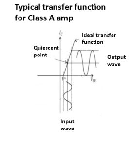
The Class A amplifier biases the amplifying device in the middle of its linear range with conduction through 360⁰ of the sine wave; this results in low distortion but low efficiency as well.
The Class A amplifier provides high linearity and low distortion. Here, the active elements (originally vacuum tubes, now almost always transistors) are biased so their quiescent operating point is in the linear part of their conducting region. The input signal induces small-to-moderate excursions around this point, thus maintaining linearity of the input/output transfer function. The active amplifier element is always on and never cut off, regardless of the magnitude or polarity of the input, as the Class A amplifier has a 360⁰ conduction angle, meaning it is on and conducts throughout a full cycle of the input sine wave.
While a properly designed Class A amplifier is capable of excellent performance and was used for many years as the primary audio-amplifier topology, it has a major drawback in that it is inherently inefficient (on the order of 20 to 30% efficiency). The reason is its constant operation in the active region which forces it to dissipate power even when there is no or just a small input signal. Largely for this reason, alternatives to Class A were devised.
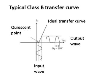
Class B uses a complementary pair of devices biased at cutoff, with 180⁰ of conduction. This boosts efficiency significantly.
The Class B amplifier uses a “push-pull” arrangement with a pair of complementary amplifier elements (such as PNP/NPN transistors or N-/P-channel MOSFETs), each biased at cutoff with the conduction angle of each amplifier at 180⁰ (half cycle). When the bipolar, zero-centered input signal goes positive, one amplifier comes out of cutoff and goes into its active region, conducts, and amplifies; when the signal goes negative, the other amplifier does the same while the first one is cutoff and thus dissipating near-zero power.
The Class B amplifier can have efficiency in the 30-40% range, far better than Class A although still unacceptably high for many applications. Also, it suffers from crossover distortion which generates harmonics, arising because of the slight lag or discontinuity as one active element turns on while the other turns off (and vice versa). Distortion is typically between 10 and 20%. This may be acceptable for some situations but not for higher-quality audio designs.
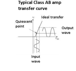
Class AB overcomes the crossover distortion of Class B by biasing the devices slightly into the cut-off region, with >180⁰ of conduction. There is an efficiency penalty to this approach.
The Class AB amplifier is a blend of Class A and Class B, and strives to offer a compromise in efficiency and performance. In this topology, each of the pair of complementary active elements is biased slightly into the active region, and so there is some overlap between the two at the turn-on/turn-off center point, Figure 3. This reduces distortion to a low level – typically 1% and even down to 0.1% – at a slight increase in power dissipation. There is a tradeoff between conduction angle, which is somewhat greater than 180⁰, and resultant distortion, with increased conduction angle and associated dissipation yielding lower distortion. Until the development of advanced, digitally driven audio amplifiers, Class AB was the most commonly used audio amplifier approach.
The Class C amplifier offers the highest efficiency, but has poor distortion qualities and generates many undesired harmonics. In Class C, the amplifier conduction angle is far less than 180⁰, and it is biased so it only turns on for large signal excursions. The output current and thus dissipation is zero for more than the one-half of the input signal.
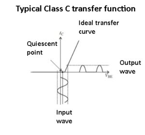 The efficiency of Class C amplifiers can be fairly high, up to about 70-80%, but because the distortion is also high (10 to 30%) the Class C approach cannot be used for audio. However, it is used for higher-power RF transmitters, where dissipation must be kept to acceptably low levels. To make the Class C amplifier usable, the undesired RF harmonics are removed by using a resonant output circuit as a low-pass filter.
The Class D amplifier (sometimes called a digital amplifier, though this is misleading) is a somewhat counterintuitive yet effective topology. Instead of a linear or quasi-linear approach as with the other classes, it functions as a nonlinear, switching amplifier. The active element is either fully on or fully off and is pulse-width modulated by the input signal. The output waveform is switched at a frequency which is far higher than the highest audio signal to be amplified.
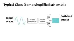 As a result of this fully on/off action, efficiency can approach 100%. The switching on/off output is low-pass filtered to restore the desired analog waveform shape with distortion of about 0.1 to 1%. Class D is now the dominant audio amplifier approach for PC audio cards, mobile devices, and automotive audio systems because of its attractive combination of performance, efficiency, and small size.
The Class A, B, AB, C, and D amplifier designations are standardized, fully defined, and widely recognized. Now we’ll look at a few other topologies which are less well known but also used.
The Class G amplifier resembles the Class AB amplifier except that it uses two or more supply voltages, one a lower voltage, the other a higher voltage. It is used exclusively for audio applications. When the power output demand is at a lower level (as set by the user or the application), the amplifier automatically uses only the lower-voltage rail. However, when the desired output signal power rises, the Class G amplifier automatically switches to the higher supply voltage. As a result, this amplifier is more efficient than Class AB amps because it uses the maximum supply voltage only when beneficial, while Class AB amplifiers always use the maximum supply voltage.
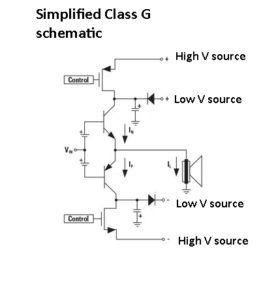
The Class G amplifier uses bipolar lower-voltage and high-voltage rails, with a control signal which switches the higher voltage in and out via a pair of MOSFETs.
Note there is a potential issue with implementing a Class G amplifier in that usually only a relatively low voltage is available in portable or battery-powered applications. To compensate, the Class G amplifier often comes with a charge-pump voltage converter to generate a second, higher-value rail voltage. Of course, the charge pump is not 100% efficient so it is important to make sure the potential efficiency gain from using that second, higher-voltage rail is not negated by the losses in the charge-pump voltage booster.
The Class H amplifier, also suitable only for audio applications, resembles the Class G design. It adjusts its supply voltage to minimize the voltage drop across the output stage and thus minimize associated losses. Depending on the specific approach, the Class H amplifier may use multiple discrete voltages or even a continuously adjustable supply. This topology does not require multiple power supplies because it uses (and adjusts) the existing power rail via a feedback loop between output power level and supply-rail value.
The Doherty Amplifier does not have a letter designation but instead uses the name of its developer. It was first implemented in the 1930s and is applicable only for RF amplification. As with other amplifier topologies, it is intended to minimize inefficiency and dissipation. It is especially useful when there is a large range between average signal power and peak signal power.
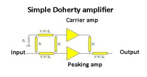
The Doherty amplifier splits and sends an input RF signal to a less-efficient Class AB amplifier for lower-power needs and to a higher-efficiency Class C booster for higher-power amplification.
The Doherty amplifier uses two amplifiers, with one as a “carrier” amplifier biased as Class AB, the other as a “peaking” amplifier biased for Class C operation to provide a high-efficiency power boost when needed for higher-power input excursions. This topology was rarely used for many decades partially because of its complexity as well as its non-intuitive nature and RF-only aspects. But it is now receiving a great deal of attention because it’s efficient when amplifying the complex waveforms of various smartphone modulation schemes.
In operation, the input signal is evenly split using a 3-dB quadrature coupler. The two outputs from the coupler are 90⁰ out of phase and are brought back into phase and reactively combined using the quarter-wave transmission line of the peaking amplifier. The two signals in parallel create an impedance of Z0/2 Ω which is stepped up to Z0 Ω by the quarter-wave transformer. Clearly, this is a complex operation with RF lines, couplers, impedance transformers and more, but it yields high efficiency for signals with high peak/average ratios.
Other less common and less standardized amplifier designations include the Class E design which uses LC tank circuits for filtering (like class C amplifiers) but where an active device becomes a switch. There are also Classes F, S, and T amplifiers, but these are highly specialized and primarily offer small variations on the better-known classes.