• Skip to primary navigation
  • Skip to main content
  • Skip to primary sidebar
  • Skip to footer

Electrical Engineering News and Products

Electronics Engineering Resources, Articles, Forums, Tear Down Videos and Technical Electronics How-To's

  • Products / Components
    • Analog ICs
    • Battery Power
    • Connectors
    • Microcontrollers
    • Power Electronics
    • Sensors
    • Test and Measurement
    • Wire / Cable
  • Applications
    • 5G
    • Automotive/Transportation
    • EV Engineering
    • Industrial
    • IoT
    • Medical
    • Telecommunications
    • Wearables
    • Wireless
  • Learn
    • eBooks / Handbooks
    • EE Training Days
    • Tutorials
    • Learning Center
    • Tech Toolboxes
    • Webinars & Digital Events
  • Resources
    • White Papers
    • Design Guide Library
    • Digital Issues
    • Engineering Diversity & Inclusion
    • LEAP Awards
    • Podcasts
    • DesignFast
  • Videos
    • EE Videos and Interviews
    • Teardown Videos
  • EE Forums
    • EDABoard.com
    • Electro-Tech-Online.com
  • Bill’s Blogs
  • Advertise
  • Subscribe

Breadboards evolve to meet 21st-century design needs, Part 2: Recent past and present

May 19, 2022 By Bill Schweber

The classic wooden breadboard is obsolete, but its name continues to refer to a vital engineering tool that has changed to meet today’s component and design realities.

As leaded components such as discrete transistors and low-pin-count ICs in DIP packages came into use in the late 1960s and 1970s, breadboarding technology also evolved. Among the popular options were “solderless” breadboard, which are still available in many configurations (Figure 1). They are convenient, accessible, easy to use, and support a reasonable component density.
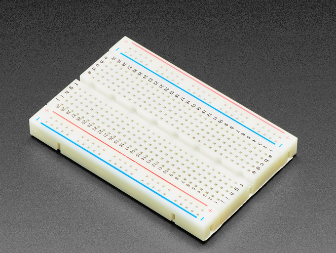
Fig 1: This basic solderless breadboard was very popular with DIP ICs and leaded components and is still widely used. (Image: Adafruit)

A more advanced example is the PB-104M Externally Powered Solderless Breadboard Assembly from Global Specialties, which is well-suited for prototyping low-frequency circuits (Figure 2). It is mounted in a 21 × 24 cm frame (9.45” L × 8.27” W) and includes 3220 tie-points, four binding posts for connecting power supplies, and supports 28 16-pin ICs; jumpers are made using 0.4 to 0.7-mm diameter wire stripped at the end. The key to the versatility of this breadboard is that the holes are spaced 0.1 “apart to accommodate standard DIP components as well as the pins of adapters and headers, in addition to wire leads.
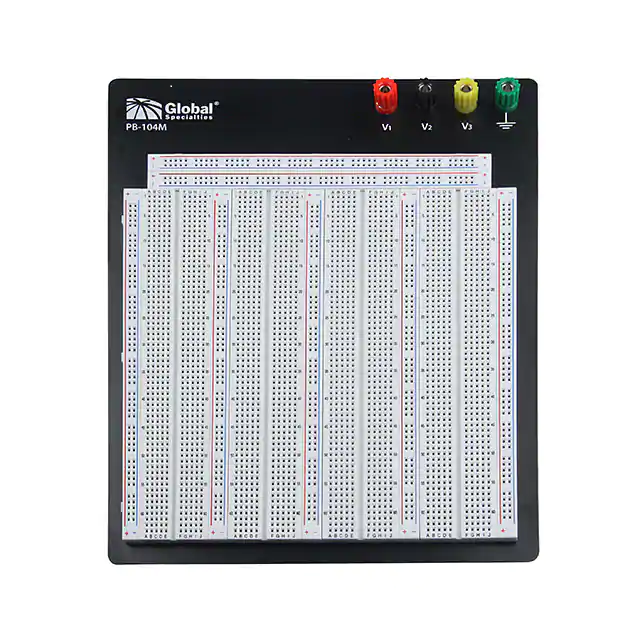
Fig 2: This PB-104M solderless breadboard assembly from Global Specialties accommodates multiple DIP ICs, DIP-footprint adapters, discrete components with wire leads, and individual wire jumpers. (Image: Digi-Key/Global Specialties)

If you do a web search, you’ll see many experimenters still using these for projects based on discrete leaded devices (transistors, LEDs, switches. Depending on the project and the designer, they can be neat and tidy (Figure 3) or evolve into somewhat of a messy arrangement (Figure 4).
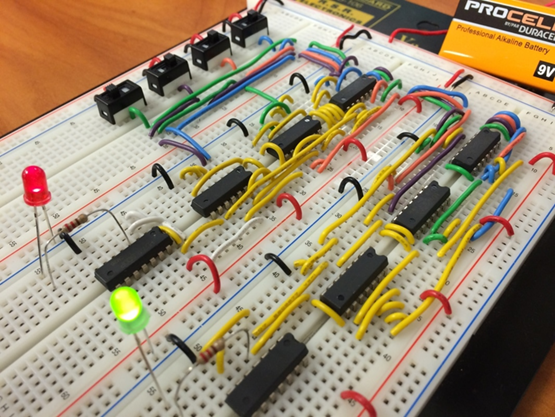
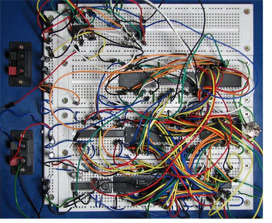
Fig 3: The solderless breadboard and DIP/leaded components can be used to create a neat demonstration circuit. (Image: Randunut)
Fig 4: Care and self-discipline are needed when installing the jumpers for anything but the smallest project in a solderless breadboard; otherwise, a maze of indecipherable wires is the result. (Image: Wikipedia)


The practicality of such solderless breadboards is limited for an obvious and a not-so-obvious reason. The obvious reason is the tiny size and/or high-density nature of many passive and IC components. In some cases, it is possible to substitute a leaded resistor for a chip resistor measuring just a few millimeters on a side. Still, you can’t replace a 100+ lead (often as bumps rather than actual leads), tight-pitch IC with its lower-density counterpart. In fact, even many of the latest low-pin-count ICs, such as 8-lead op amps, are only offered in tiny surface-mount (SMT) packages without DIP counterparts.

But there’s a second, less obvious reason why such traditional breadboarding is no longer feasible or even desirable. Before microcontrollers, microprocessors, high-functionality ICs, and software “took over,” analog and basic digital circuits had a linear signal flow from input to output. For example, a public-address system amplifier would have a preamplifier stage to interface with the microphone, followed by filter stages to shape the response and attenuate noise, then a low-level power amplifier/driver to boost the signal, and finally, a power amplifier to deliver the higher-power output for the speakers.

In that typical design process, these stages would be built, tested, and added to each other in sequence while checking signal flow at and through each stage to ensure there were no unintended interactions in overall signal flow and integrity and similar; there was an analogous situation for basic digital-logic ICs as they “processed” a signal.

Now, however, a typical system consists of high-functionality blocks that interact with each other and, most critically, with the system processor. There is a significant amount of back-and-forth signal and data flow among all these blocks, which can range from a low-speed, highly sensitive sensor amplifier to an RF link for Wi-Fi or Bluetooth, as well as the user interface other I/O. There is no single flow path from input to output; instead, it is a web-like topology with the various elements linked to each other.

This arrangement of signal paths requires a different approach to development, debugging, and testing and, therefore, different breadboard tools, which will be discussed in Part 3.

EE World Related content

Mounting base kit simplifies electronic prototyping tasks
Understanding delay for I/O: Using Arduino functions vs. coding the MCU
Plug-And-Play Diagnostic Devices
Considerations in PCB layout guidelines
Getting started in electronics: core components
What is a Board Support Package?
A “canned” module/IC solution simplifies wireless implementation, but potential design-in issues remain

External references

Wikipedia, “Fahnestock clips”
Schmartboard Breadboard Systems
Phase Dock Inc., Universal WorkBench system

 

You Might Also Like

Filed Under: Analog IC Tips, FAQ, Featured, PCB Design Tagged With: breadboards, FAQ

Primary Sidebar

EE Engineering Training Days

engineering

Featured Contributions

GaN reliability milestones break through the silicon ceiling

From extreme to mainstream: how industrial connectors are evolving to meet today’s harsh demands

The case for vehicle 48 V power systems

Fire prevention through the Internet

Beyond the drivetrain: sensor innovation in automotive

More Featured Contributions

EE Tech Toolbox

“ee
Tech Toolbox: Internet of Things
Explore practical strategies for minimizing attack surfaces, managing memory efficiently, and securing firmware. Download now to ensure your IoT implementations remain secure, efficient, and future-ready.

EE Learning Center

EE Learning Center
“ee
EXPAND YOUR KNOWLEDGE AND STAY CONNECTED
Get the latest info on technologies, tools and strategies for EE professionals.
“bills

R&D World Podcasts

R&D 100 Episode 10
See More >

Sponsored Content

Advanced Embedded Systems Debug with Jitter and Real-Time Eye Analysis

Connectors Enabling the Evolution of AR/VR/MR Devices

Award-Winning Thermal Management for 5G Designs

Making Rugged and Reliable Connections

Omron’s systematic approach to a better PCB connector

Looking for an Excellent Resource on RF & Microwave Power Measurements? Read This eBook

More Sponsored Content >>

RSS Current EDABoard.com discussions

  • Audio Switching
  • BOM sent to Contract assemblers doesnt correspond to schem
  • 12VAC to 12VDC 5A on 250ft 12AWG
  • Amperage changes in DC-DC conversion
  • AC amplifier, transistor with bias network

RSS Current Electro-Tech-Online.com Discussions

  • stud mount Schottky diodes
  • LED circuit for 1/6 scale diorama
  • using a RTC in SF basic
  • Hi Guys
  • Can I use this charger in every country?
Search Millions of Parts from Thousands of Suppliers.

Search Now!
design fast globle

Footer

EE World Online

EE WORLD ONLINE NETWORK

  • 5G Technology World
  • Analog IC Tips
  • Battery Power Tips
  • Connector Tips
  • DesignFast
  • EDABoard Forums
  • Electro-Tech-Online Forums
  • Engineer's Garage
  • EV Engineering
  • Microcontroller Tips
  • Power Electronic Tips
  • Sensor Tips
  • Test and Measurement Tips

EE WORLD ONLINE

  • Subscribe to our newsletter
  • Teardown Videos
  • Advertise with us
  • Contact us
  • About Us

Copyright © 2025 · WTWH Media LLC and its licensors. All rights reserved.
The material on this site may not be reproduced, distributed, transmitted, cached or otherwise used, except with the prior written permission of WTWH Media.

Privacy Policy