I briefly mentioned the Miller effect in an earlier blog on cascode amplifiers but thought it was worthy of a more detailed discussion. The Miller effect or Miller capacitance was first published by John M Miller in 1920 – “Dependence of the input impedance of a three-electrode vacuum tube upon the load in the plate circuit.” While it relates to vacuum tubes, the same concept exists in bipolar transistors, JFETs, MOSFETs etc. The easiest way of understanding the cause is probably with a simple example.
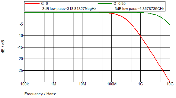
 This example shows an idealized inverting amplifier with a 50Ω source impedance and 10pF of capacitance from the output to the input. The amplifier could be bipolar, MOSFET or even a vacuum tube. In this example, the only input impedance is due to the feedback capacitance C1. In the case of a bipolar amplifier the capacitance would be the collector-base capacitance but there would also be a resistive component to the input impedance. If you set the gain as zero you will find the input (after the 50Ω resistor) has a bandwidth of 318MHz. If you set the gain to -10 you will find the input bandwidth is reduced to 29MHz.

This dramatic drop in bandwidth is due to the combination of the gain and the feedback capacitance C1. The reduce in bandwidth is 11 times due to the gain of -10. A gain of -1 would have halved the gain to 159MHz. The explanation is fairly straightforward if you imagine the input voltage charging the capacitor through the resistor as your starting point. With no gain i.e. the amplifier output at zero volts, the current through the resistor will charge the capacitor as expected. When you have some gain, as you charge the capacitor through the resistor, the opposite end of the capacitor will be moving at 10 times the rate in the opposite direction. So, it feels like you are charging a capacitor 11 times the size.
So, to design a high bandwidth amplifier you might need to consider ways of reducing the Miller effect. One such method described in an earlier blog is the cascode amplifier (not to be confused with a cascade amplifier).
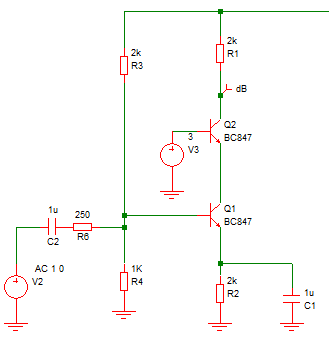
A bipolar cascode, as shown above, works by preventing the collector voltage of the input transistor from moving much, so the Miller effect is greatly reduced. The circuit still works as an amplifier because the current from Q1 collector can still pass through Q2 to the load resistor. Q2 doesn’t suffer from Miller effect from collector to base because the input to Q2 is the emitter not the base. The base voltage is fixed.
In fact, Q2 configuration is a common base amplifier – one of the configurations which don’t suffer from Miller effect, although you can simply consider it as a device which passes current to the load. Another method of reducing the impact of the Miller effect is to reduce the source resistance but that is not always practical so “active” methods such as the cascode are usually used. With the cascode configuration the transistors need not be the same type. You can mix a JFET with a bipolar transistor, for example, or use two JFETs.
An interesting diversion from the earlier description of the Miller effect is that if the gain was not inverting and the gain was unity, you actually have a “bootstrap” circuit. The bootstrap concept can be explained in different ways, but referring back to the original schematic but with a unity gain and not inverting, as you try to charge the capacitor through the input resistor the voltage on the opposite end of the capacitor will move in the same direction so no current flows in the capacitor and it doesn’t actually get charged (and so doesn’t appear to be there as it has no effect). The schematic below shows the configuration (a voltage follower).
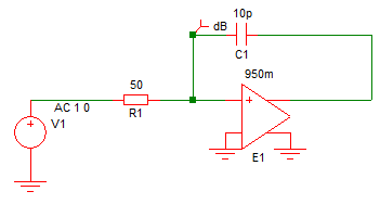
In reality, your gain is likely to be something other than unity, but if you apply a gain of 0.95 you will find the input bandwidth is 6.4GHz compared to the 318MHz with no gain, i.e. 20 times higher. A bipolar emitter follower might be the place where you get a buffered signal with a gain approaching unity. You need some sort of buffer because you need to be able to drive the non-input end of the capacitor with an impedance lower than the input impedance of the amplifier and signal source. The graph below shows the improvement by bootstrapping with a gain of 0.95.
 While bootstrapping can be used to reduce the effect of device input capacitance, it can also be used to increase input impedance or to minimize the effect of the capacitance of another device such as a photodiode. For example, the feedback from an input buffer could be used to drive the non-active end of a photodiode to reduce its effective capacitance.


Leave a Reply
You must be logged in to post a comment.