The modern MRI system is an amazing blend of diverse technologies, based on the realization that a small but critical aspect of the spin of hydrogen nuclei could be leveraged to provide a safe, non-invasive way to see inside a human body.
Magnetic resonance imaging (MRI) is an extraordinarily valuable and vital tool for non-invasive imaging of soft organs, tissue, and structures within the human body (or other objects which have a high water content). This FAQ will explain the basic operating principles as well as the history of its development and subsequent legal issues. An MRI system is a remarkable combination of electronics, magnetics, supercooling, software, and many other technologies, and is based on subtle atomic-level principle.
The other two widely used imaging technologies – X-rays and ultrasound – are straightforward in concept. X-rays use wavelengths which penetrate skin and organs to varying extents but are otherwise like a photograph on film, while ultrasound is an implementation of well-understood echo principles. Both were initially implemented without an understanding of deep physics and had a direct connection between the principles and the outcome. In contrast, the principles of MRI are based on atomic-level understanding and are not at all obvious, and could not be envisioned without that physics; it is a very non-intuitive and “mysterious” technique.
Q: Was magnetic resonance imaging always known by that name?
A: No, it was originally called nuclear magnetic resonance (NMR) imaging. The “nuclear” part was dropped because it scared people: they thought they were being irradiated, which is not the case at all. MRI uses magnetic fields and non-ionizing radio frequency waves at very low levels and has no relation to the public’s concept of “nuclear.” Further, even intense magnetic fields have never demonstrated any health impact.
Q: What are the key principles needed to understand how MRI works and why it can be applied to imaging?
A: First, there’s the atomic basis. The magnetic moments of an atom’s nucleus (composed mostly of protons and neutrons) tend to align either parallel or anti-parallel to an external magnetic field. Second, it’s the medical knowledge that different organs (and tumors) contain different amounts of water and thus more hydrogen atoms, and this difference can be exploited.
Q: What’s a spinning nucleus and magnetic fields have to do with imaging?
A: Like a common spinning top, the atomic nucleus precesses about the direction of the magnetic field alignment and at a frequency that depends on the magnetic field’s strength and the atom’s nuclear magnetic moment. The magnetic moments of nuclei can be induced to flip their orientation if they absorb energy from an imposed electromagnetic wave of the right frequency.
Q: Then what can happen?
A: They also emit this absorbed energy when they fall back to their lower-energy orientation, a transition that can be detected when the energy beam is exposed to a radio frequency signal as it travels through the magnetic field. Tuning either the external magnetic field or the radio frequency can produce resonance.
Q: How do water and hydrogen play into this?
MRI-induced radio signals from cancerous tissue will differ from those of healthy tissue, for example. Specifically, tumor tissues will have a longer relaxation time to recover and return to their unenergized state. In the presence of an intense imposed magnetic field, the protons absorb energy, and their axes line up to create a single magnetic vector; they radiate this energy when the magnetic field is removed. The entire nuclear basic for MRI is all very abstract and is an almost “magical” occurrence, as it is totally invisible and almost impossible for most people even to envision.
Q: What’s the situation when there is no external magnetic field?
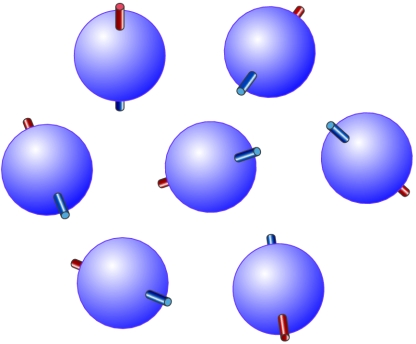
A: Without an external magnetic field, protons (hydrogen nuclei) are randomly oriented. For imaging purposes, the hydrogen nucleus (a single proton) is used because of its abundance in water and fat. Under normal circumstances, these hydrogen protons are “bar magnets” which spin in the body with their axes randomly aligned, Figure 1.
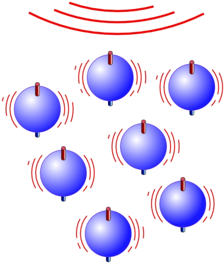
Q: What happens when that external magnetic field is applied?
A: When the body is placed in the magnetic field of the MRI scanner, the axes of these protons line up, Figure 2. This uniform alignment creates a magnetic vector oriented along the axis of the MRI scanner.
Q: How strong is the externally applied magnetic field?
A: Very strong: MRI scanners use different magnetic-field strengths beginning at about 0.5 and 3 tesla (T; 1 T = 10,000 gauss) as a minimum value; higher field strengths result in improved resolution. This field intensity can be created only using high-current superconducting magnets cooled by liquid helium to nearly absolute zero. For comparison, the Earth’s magnetic field at the surface ranges from 25 to 65 microteslas or 0.25 to 0.65 gauss.
Q: What happens after the field is applied?
A: When additional energy in the form of a radio wave is added to the applied magnetic field, the magnetic vector is deflected. The radio frequency (RF) wave that causes the hydrogen nuclei to resonate is dependent on the target element (here, hydrogen) and the strength of the magnetic field. To make the MRI work, the strength of the magnetic field in smaller, gradient magnets (about 200 gauss) is electronically altered from head to toe by using a series of gradient electric coils. By altering the local magnetic field, different slices of the body resonate as the different frequencies are applied.
Q: How is this implemented in practice?
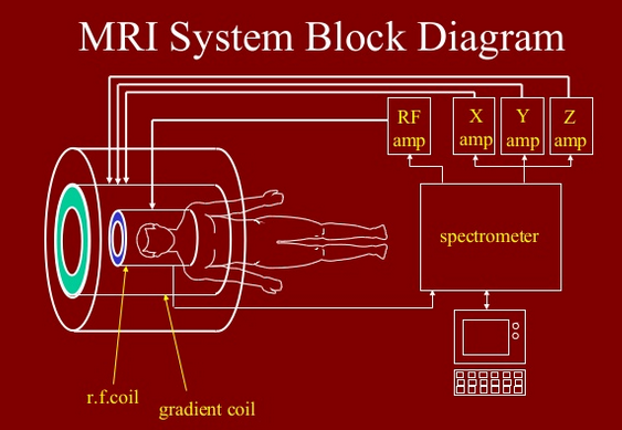
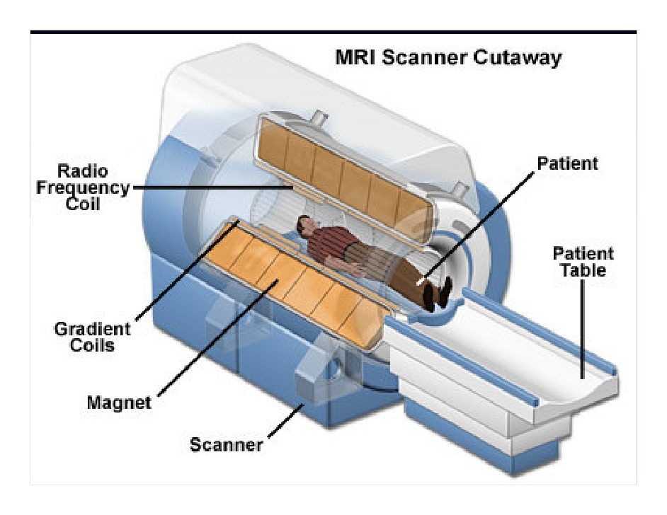
A: In practice, the MRI scanner contains two magnets. The first one is has a static field and causes all of the body’s water molecules to align in one direction. The second magnetic field is then switched on and off in a series of quick pulses. These pulses cause each hydrogen atom to alter its alignment and then revert to its original, relaxed state when switched off. As a result of the gradient coils being switched on and off, the magnetic coil vibrates. This creates a loud knocking sound inside the scanner. An MRI machine is a very complicated system, Figure 3 and Figure 4.
Q: What happens when that external RF source is switched off?
A: When the external RF source is switched off, the aggregate magnetic-moment vector returns to its resting state, and the proton emits an RF signal. This is the signal that creates raw data for images. An array of sensitive receiver coils with high-gain, low-noise amplifiers is located around the body and acts as antennas to detect the emitted signal.
The time taken for the protons to fully relax is measured in two ways. T1 relaxation is the time that the magnetic vector takes to return to its resting state, Figure 5. T2 relaxation is the time needed for the axial spin to also return to the resting state, Figure 6.
Q: If the MRI “output” is received radio waves, where does the two-dimensional image come from?
A: The MRI does not inherently create a two-dimensional image; instead, the intensity of the received signals is plotted on a grayscale and cross-sectional images are built up using image-processing algorithms. The signals from the first MRI (more on this below) took several hours to process numerically; today’s MRI scan results are near real-time due to the orders-of-magnitude increase in basic CPU power, graphics engines, and other hardware and software improvements.
Q: Is there any relationship between MRI systems and a conventional microwave oven?
A: No. A microwave oven generates electromagnetic energy at the natural resonance frequency of water molecules (2.450 GHz — right in the ISM band used for Wi-Fi). This causes the molecules to vibrate and thus heat up. Also, there is no magnetic-field aspect to a microwave oven.
Q: Is there a larger lesson in the development of MRI, from basic atomic physics to the huge instruments in widespread use?
A: MRI is an excellent example of where developments across multiple disciplines (atomic-level insight, supercooling and intense magnetic fields, digital algorithm processing, low-noise RF amplifiers, power RF amplifiers, to cite just a few) enable unforeseen advances in unrelated fields (medical imaging). The technology also serves up an example of how a fundamental discovery with no apparent practical use can become the basis for a revolutionary new technique, product and industry.
Part 2 of this FAQ will explore the history of the MRI, from those who developed the underlying physics understanding (with no concept of MRI) to those who realized it could be adopted and used. “
References
- Damadian, “Field-focusing n.m.r. (FONAR) and the formation of chemical images in man”
- APS News, “MRI Uses Fundamental Physics for Clinical Diagnosis”
- Two Views, “The History of MRI”
- Thought Co., “Magnetic Resonance Imaging MRI”
- US National Library of Medicine, National Institutes of Health, “Magnetic resonance imaging”
- Fonar, Inc, “MRI History Timeline”


Very useful article
Excellent article for the layman, me. The complexities are amazing and then the minds that determined how all this could benefit everyone is quite amazing. There are very smart people in this world. Thanks for this.
Excellent article! Very “lay-person” accurate.
Having been involved (manufacturing and quality) for 7+ years in the MRI world,
I take issue with only one statement; “Further, even intense magnetic fields have never demonstrated any health impact”. This is not true, especially for the brain. Evidence of dis-orientation (probably temporary and not permanent) begins at about 1.5T and I am certain that higher intensity will cause damage. In the manufacture of the MRI machines, much effort was taken to make sure these bounds were not violated.
EAR PROTECTION IS REQUIRED
Hi Bill,
Excellent article.
I went from CT Detector/DAS system design, to MRI Gradients & RF, to Ultrasound Front Ends. We joked about our MRI magnetics scrambling any magnetite or lodestone in our brains – the same stuff pigeons use for navigation – and the effect would leave us confused and euphoric. We never confirmed the magnetite. Euphoria is common to all emerging technology designers.