Part 1 looked at of isolators and circulators, which are basic RF/microwave passive devices. This part looks at couplers and splitters, which are two other basic passive devices. (Attenuators are another important class of passive RF/microwave devices. They are not covered here.)
A: How is coupling and splitting done in the non-RF/microwave world?
A: In the non-RF world, it is relatively easy to couple two or more signals or split a signal into two or more signals, simply by using op amps and resistors. Figure 1 shows a basic combining (summing) circuit.
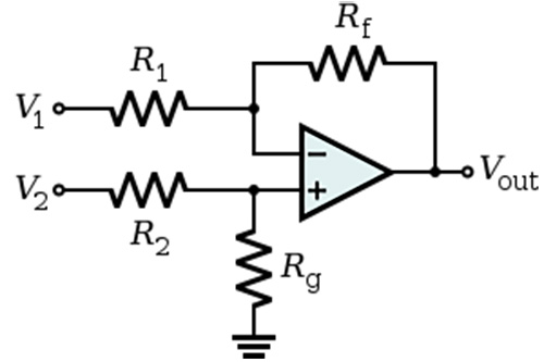
Fig 1: An op amp and resistors can be used to implement a multi-input summing circuit; by selection of the various resistor values, the different inputs can be independently scaled to the desired magnitude. (Image source: Wikipedia)
The complementary function of splitting a signal can be accomplished with a simple resistive voltage divider, although that approach has many weaknesses. Instead, op amps can be used to buffer the split signals and make sure that there is no interaction between the various outputs (Figure 2).
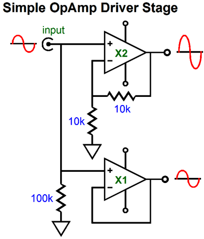
Fig 2: Resistors and op amps can also be used to scale and divide a single input signal into multiple outputs (here, for voltage signals, but a similar arrangement works for current); again, each channel’s magnitude is individually scalable. (Image: Tubecad)
Q: Does this approach work for RF/microwave signals?
A: It does not work as the frequency gets higher, or the power levels increase. For RF and microwave signal power, very different approaches are needed. Like the op-amp design, the microwave summing circuit – called a coupler – is directional in that the flow of energy has a specific direction defined by design. Therefore, these couplers are often called directional couplers.
Q: What is a directional coupler?
A: It is a four-port device (Figure 3), where Port 1 is the incident port, Port 2 is the through port (because it connects via a straight line). Port 3 is the coupled port, and Port 4 is the isolated port. Alternatively, a signal can be incident on Port 2, so Port 1 is the through port, Port 4 is the coupled port, and Port 3 is the isolated port.

Fig 3: A directional coupler is a four-port device characterized by signal flow and paths, and quantified using S-parameters in addition to more-common basic parameters. (Image: TutorialsPoint/Microwave Engineering)
Q: What are the primary parameters for a directional coupler?
A: First, as with most microwave devices, S-parameters are needed to characterize performance fully. The basic specifications are similar to those of other microwave components. Assuming Port 1 is the incident port, then there Insertion Loss (IL) between Port 1 and Port 2; Isolation (I – the ratio of incident power to the back-reflected power) between Port 1 and Port 4; Coupling (C – the ratio of incident power to the forward power) between Port 1 and Port 3; and Directivity (D – the ratio of forward power to the back power) between Port 3 and Port 4; all are expressed in dB, of course.
Q: How is a directional coupler actually built?
A: There are two common ways: using waveguides or using transmission lines (and there are many sub-variations, of course). A basic waveguide coupler uses precisely spaced and sized holes which are a function of wavelength and bandwidth (and the holes may have non-round shapes) to allow power to flow between two physically aligned waveguides (Figure 4). As a result, incident energy on Port 1 mixes with energy incident on Port 3.
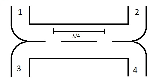
Fig 4: A waveguide coupler uses precise physical placement of two waveguides with carefully spaced, sized, and even shaped holes to allow the desired RF energy to pass from one to the other. (Image: Microwaves101)
Q: What about transition-line couplers?
A: Obviously, many applications cannot use waveguides due to their size, cost, and other issues. An alternative in some cases is the coupler based on the RF transmission line. It uses a pair of precisely dimensioned, unshielded transmission lines placed in careful alignment with each other (Figure 5). The lines can be discrete transmission lines or even PC-board stripline/microstrip implementations.
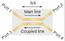
Fig 5: Unshielded, physically aligned transmission lines of appropriate length (usually quarter-wavelength – λ/4) can be used for directional couplers. (Image: Wikipedia)
Q: What about splitters?
A: Splitters are the complement of couplers and have many similarities. A splitter – also called a power divider – takes some of the incident energy and diverts it to another port. The proportion that is “split off” can be half for each port, or it can be a small fraction (such as somewhere between 1% and 10%) needed to sample the incident signal for test and measurement purposes
Q: How is a splitter implemented?
A: As with couplers, there are many ways to do this. One widely used approach is the Wilkinson power divider, which uses a split transition line (Figure 6), built by physical lines or, again, as PC-board stripline/microstrip.
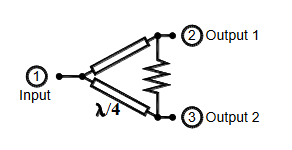
Fig 6: The Wilkinson power divider is a widely used power-splitting arrangement which is based on transmission lines which diverge but have a common termination impedance. (Image: Marki Microwave)
This has been a very brief introduction to basic passive RF/microwave components. Despite their functional simplicity, they are actually quite complicated in their details and are the subject of many detailed types of analysis ranging from academic to hands-on. Much of the advanced analysis requires the use of EM field theory, matrix and other advanced math concepts, S-parameters, and more. These RF/microwave passive components – as just about everything else in a GHz+ design – is a complicated subject in theory and in practice.
EE World Online References
Coax power splitters/dividers, directional couplers, attenuators cover dc to 110 GHz
Single-input, dual-output power splitter designed for mid- and high-end smartphones, tablets
Coaxial components cover frequencies from dc to 110 GHz
Cross guide couplers with 4, 3 or 2 waveguide ports work across C to K bands
Cross-guide waveguide couplers carry up to 4-port interface
Waveguide directional couplers work up to 33 GHz
Surface-Mount Bi-Directional coupler provides 200W power handling from 225 to 450 MHz
References
- Wikipedia, “Isolator (microwave)”
- Wikipedia, “Circulator”
- Nova Microwave, “Understanding Circulators & Isolators”
- MECA Electronics, “Isolator/Circulator Basics”
- Microwaves & RF, “A Primer on Circulators and Isolators”
- Microwaves101, “Circulators”
- Microwave Journal, “Recent Advancements in mmWave Isolator Technology”
- Microwaves101, “Directional Couplers”
- TutorialsPoint, “Microwave Engineering – Directional Couplers”
- SlideShare/LinkedIn, “Microwave Couplers”
- Marki Microwave, “Microwave Power Dividers and Couplers Tutorial”
- Wikipedia, “Power dividers and directional couplers”


Leave a Reply
You must be logged in to post a comment.