In recent years, considerable attention has been focused on power factor (PF) and power factor correction (PFC) in devices ranging from small appliances to larger systems. Concern about PF and PFC is not new: it has been an issue with AC power delivery in industrial and commercial settings for many decades. The big difference is that now even small devices, ranging from LED bulbs to AC/DC wall chargers, flat screens, refrigerators, and similar are now under scrutiny for their power factor. Depending on the power level, some sort of correction to power factor may need to be added to the design, to bring it into compliance with regulatory standards.
Q: What is power factor?
A: Power factor is a number which characterizes the phase relationship between the current and voltage on an AC power line, Figure 1. It is simply the ratio of the “real” power flowing to a load compared to the “apparent” power in the circuit. Real power is the ability of the system to do work, while apparent power is the product of the measured current and voltage of the circuit. To distinguish between the real power and the apparent power, the real power is characterized in watts, while the apparent power is called volt-amperes.
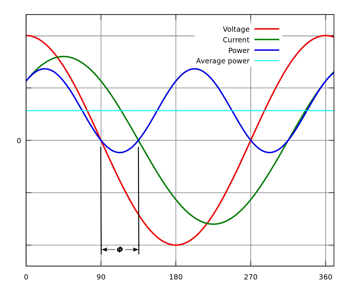
Fig 1: Instantaneous and average power of an AC voltage and current with an inductive-load power factor, at an angle ϕ of 45°, (cosine ϕ and therefore PF is ≈ 0.7). The blue line shows some of the power is returned to the grid during the part of the cycle labeled ϕ φ {displaystyle varphi } . (Image source: Wikipedia)
Q: Why is apparent power equal to or greater than the real power?
When energy stored in the load due to the load’s capacitance or inductance, and then returned to the source at a different point in the AC-line cycle, the apparent power will be greater than the real power. Another cause is that a non-linear load (more on this later) distorts the wave shape of the current being drawn from the source.
Q: What is the range of PF?
A: PF is a dimensionless parameter that ranges from 0 to +1. When current and voltage in phase, PF equals 1 (often called unity). When the current is not in phase with the voltage, the PF goes below unity. PF is also the cosine of the angle between the current and voltage waveforms, assuming both are sinusoidal (which may not be the case).
PF can also range from 0 to -1, as when the load actually returns power to the source, such as from a load which also may function as a source, such as reversible motor/generator in a power subsystem. Our concern here is for PFs between 0 and 1.
Q: What are the sources of non-unity PF?
A: There are two causes. First, linear inductive loads, such as transformers and motors, and linear capacitive loads, such as long cables. An inductive load results in what is called a “lagging” power factor, while a capacitive load power factor is called a “leading” power factor.
Second, and of increasing concern, are non-linear loads such as switching power supplies (with diode-bridge rectifiers at their front end) and LED drivers; they are called non-linear because the electrical characteristics of these circuits change during the operating cycle and so does the instantaneous PF, Figure 2. The voltage and current waveforms in these non-linear loads may be in phase, but their shapes induce severe AC-line distortion as well as waste power.
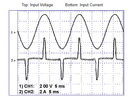
Fig 2: The voltage and current waveform relationship at the input of a switched-mode power supply is very nonlinear and results in a varying, hard-to-assess power factor. (Image source: ON Semiconductor)
Q: Why is non-unity PF a concern?
A: Again, for two reasons. First, it represents wasted power, meaning power which is generated but not put to productive use (it is usually paid for by the end user, and a sourcing burden to the power supplier). Second, the non-unity PF also manifests itself as harmonics and distortion of the normally sinusoidal power-line waveform, which causes various sorts of stresses in the power system, subsystem, and loads, especially as many of the elements in the system are designed only for 50/60 Hz operation and are not tolerant of 100/120 Hz, 150/180 Hz, and higher-frequency waveforms.
Q: When is PF a non-issue?
A: Obviously, power factor does not exist for DC power lines since there is no cyclic nature to either current or voltage, and therefore there is no meaning to the concept of “lagging” or “leading” phase between them. Further, for AC lines, PF is always 1 when the load is purely resistive and therefore is not a concern in those cases.
Q: Why is PF an increasing concern?
A: Until few decades ago, most non-industrial/non-commercial loads – primarily the residential home – consisted of resistive loads (the well-known incandescent bulb) or well-defined, linear reactive loads (mostly motors) which could be accommodated by use of a power factor correction (PFC) system at the source or local substation.
However, the modern home has many non-linear loads, such as the switched-mode power supplies (SMPS—also called switching supplies) in TV screens, computers, chargers, and LED lamps. These make it very difficult to implement PFC at the source or substation.
Part 2 of this FAQ will look at the approaches to implementing PFC.
References
- https://www.onsemi.com/pub/Collateral/HBD853-D.PDF
- https://en.wikipedia.org/wiki/Power_factor
- https://www.powerelectronics.com/power-management/power-factor-correction-justified-home
- https://home.earthlink.net/~jimlux/hv/pfc.htm

Leave a Reply
You must be logged in to post a comment.