A transmitter has much-less challenging task than the receiver. The former operates on a higher-level, known signal in a known setting, while the latter must find and decode a largely unknown signal corrupted by internal and external noise, interference from other signals, distortion, low signal levels, and constantly changing parameters.
This FAQ looks at the architectures for the wireless (RF) receiver, and how the these have evolved to meet today’s needs.
Q: What is a “receiver?” Why do we need to understand the various architectures?
A: A receiver is a system which captures a bandwidth of carrier signals within the electromagnetic spectrum, focuses on one or a few desired signals, and then recovers the encoded signal which modulated the carrier. It is the essential complement to the transmitter function of a communications link.
Q: What is the simplest radio receiver?
A: The tuned radio frequency (TRF) design is the simplest. A resonant circuit acts as a bandpass filter to select the desired signal, which may be anywhere in the spectrum from tens of kHz to many MHz. The classic crystal radio is an example of a TRF design, Figure 1.

Fig 1: The classic self-powered, entirely passive crystal radio is a simple implementation of a tuned radio-frequency receiver, but has major practical shortcomings. (Source: www.makearadio.com)
Q: Is that all it takes to receive a signal?
A: A single tuned circuit does not have the needed performance across the spectrum, so several stages of filtering are needed to hone in on the desired signal.
Q: What are the key attributes of the TRF design?
A: It’s simple, which is good, but performance across many attributes is poor to marginal. It’s difficult to filter small bandwidths across the spectrum directly, so multiple filtering stages need to be tuned simultaneously and must remain stable despite temperature, aging, and other drifts. The earliest TRF designs typically had three or four filter stages in series. Each stage had to be tuned individually, which was a time-consuming, iterative process. Later designs linked the filter stages mechanically (ganged tuning), to minimize this problem, but performance was still marginal.
Q: Is the TRF approach still used?
A: Yes, but only in very specialized and limited cases, such as when a receiver only needs to work at one frequency and not be tuned to other frequencies over a tightly constrained setting. It can be a low-cost, basic solution but has many limitations.
Q: What was the next radio receiver architecture?
A: Major Edward H. Armstrong developed the superheterodyne (often shortened to superhet) approach in the 1910-1920 period, which superseded the regenerative approach he had developed over a decade. The regenerative approach used positive feedback in a TRF design to increase gain, but was very prone to self-oscillation and other issues. (Note that Armstrong also went on to invent frequency modulation, as well.)
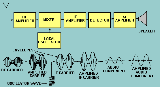
Q: What was the innovation of the superhet architecture?
A: The superhet transformed the problem of variable tuning through the use of a local oscillator and filtering for tuning, Figure 2. In brief, a local oscillator (LO) output, at a frequency which is offset from the desired signal frequency by a fixed amount (usually 455 kHz for broadcast AM radio, and 10.7 MHz for higher-frequency broadcast FM). The LO output is mixed in a nonlinear circuit with the carrier. The mixer output is two signals, one at the sum of the LO + carrier, and one their difference. The sum signal is at a high frequency and easily filtered out, and it is the difference which is of interest. This difference will always be at a fixed value of the LO offset, and is called the intermediate frequency, or IF.
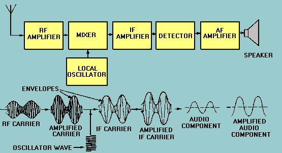
Fig 2: The basic superheterodyne receiver combines a tuned local oscillator at fixed offset from the signal of interest in a nonlinear mixer; the result is that all received frequencies are down-converted down to a single, known intermediate frequency for further processing and demodulation. (Source: TPUB/ Integrated Publishing, Inc.)
Q: Then what happens?
A: Here is where the genius of Armstrong’s approach becomes clear. Regardless of the carrier frequency being tuned, the difference will always be at the IF. That means that all subsequent amplification, filtering, and demodulation can be designed and optimized solely for that IF frequency. The fixed IF signal is then converted down to the baseband frequency, where it can be demodulated.
Q: Can the superhet be used with any type of modulation?
A: Yes, it does not matter if the modulation is AM, FM, PM, analog, or digital. The modulation type is only an issue for the final demodulating stage at baseband. The IF stages are primarily concerned with signal bandwidth and dynamic range, among other factors.
Q: What are some of the most critical elements of a successful superhet design?
A: The stability, repeatability, and purity of the LO output are among the top key factors. If the LO drifts, is hard to tune to a desired frequency or has distortion, the superhet receiver will have poor performance.
Q: How is the LO implemented?
A: For many years, it was built as an analog oscillator using vacuum tubes, and then transistors and ICs. In the last few decades, the analog LO has largely been replaced by a digitally synthesized oscillator which allows the user (or system) to set the LO frequency with great accuracy, stability, and repeatability. The synthesized oscillator uses a crystal whose single output frequency can be digitally manipulated to cover all channels in the band of interest.
Q: Can the superhet handle signals in the hundreds of MHz and even GHz range?
A: Yes and no. The standard “single-conversion superhet can. But in most cases, performance is not as good as those application need in terms of stability, tuning, sensitivity, and other parameters. However, an enhanced superhet approach called “double conversion” (and even “triple conversion”) overcomes these issues, but at the cost of more circuitry, Figure 3, including a second LO at a lower, fixed frequency. All stages operate at fixed, known-in-advance intermediate frequencies, and so can be optimized in terms of filtering, gain, bandwidth, and other parameters.
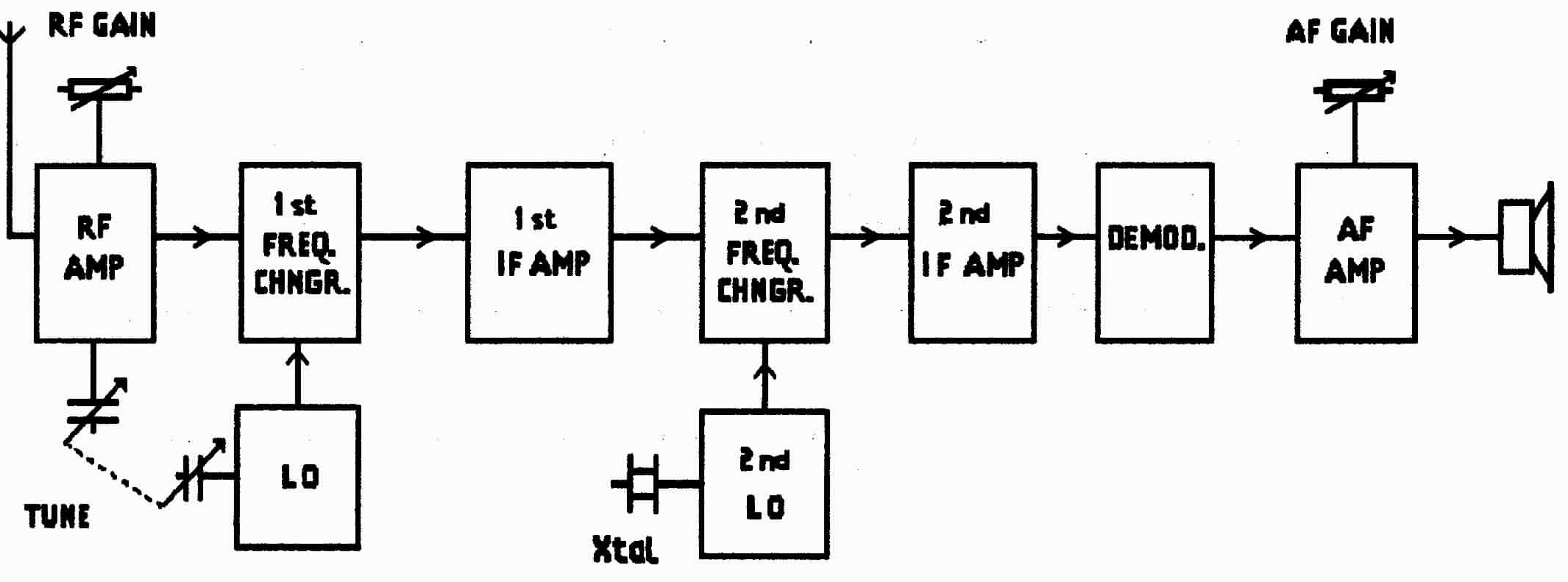
Fig 3: The double-conversion superhet receiver used for higher carrier frequencies has two down-conversion stages and two corresponding independent local oscillators, but only the first, higher-frequency one needs to be tunable; the second is at a fixed frequency. (Source: Readingrat.net)
Q: Is the superhet the “last word” in receiver architectures?
A: Again, yes and no. It is a mostly or all-analog approach that is by far the dominant one because of the excellent performance possible, the ability to select operating parameters to match the application priorities, and the huge amount of analysis insight and practical understanding that receiver designs have with it.
However, there are other approaches developed in recent years which compete with it in some situations: the “zero-IF” (direct to baseband) and the software-defined radio (SDR) architectures. These will be covered in Part 2.
Reference
University of California at Berkeley, “EECS 242: Receiver Architectures”


Leave a Reply
You must be logged in to post a comment.