High-speed, high-performance “just plug and go” wired-communications interfaces such as Ethernet and USB are in wide use. In contrast, the technically ancient RS-232 standard and related standards seem like antique museum pieces with no design-in interest.
However, that is a simplistic view of the reality. Although not necessarily the first choice or obvious choice in new designs, this standard – along with more-advanced RS-422, RS-423, and RS-485 ones – still have a role to play in both retrofit and new designs.
Q: What is RS-232?
A: It is a recommended standard (hence, the “RS” prefix) for serial interconnection between two devices, such a computer and peripheral (printer, scanner, keyboard) or between a data-acquisition device and a computer or industrial sensing/control system.
Q: Where is it used now? Why study it?
A: It is installed primarily in legacy equipment in industrial settings or scientific equipment when a subsystem must be upgraded, replaced, or interfaced with existing equipment. While the standards once were the primary way to connect a computer to a printer (even a mechanical “Teletype”), their new use in such situations is now mostly obsolete. However, there may be a need to connect a legacy RS-232 port to USB or Ethernet, and there are available adapter boxes which do that.
Q: What is the background of the standard?
A: RS-232 was first introduced in 1960 by the Electronic Industries Association (EIA) as a Recommended Standard. It was defined to allow the connection between any unit configured as Data Terminal Equipment (DTE) and any unit configured as Data Communications Equipment (DCE), over a distance of up to 50 feet. Control of the standard was eventually passed to the Telecommunications Industry Association (TIA); the current version of the standard (Revision F) was issued in 1997 and is called TIA-232-F Interface Between Data Terminal Equipment and Data Circuit-Terminating Equipment Employing Serial Binary Data Interchange.
Q: What does the standard define?
A: Unlike many of today’s standards (USB, Ethernet), RS-232 and its relatives only provide a rough framework. The standard defines three factors: signal voltages, use of the signal lines, and signal and bit timing between a DCE and a DTE. Although it does not specify what information or data the bits represent, ASCII-format is the most common encoding used.
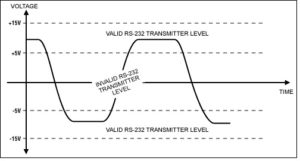
Signal voltages: originally defined with +3 to +25 V as a binary 0 (called a “space” from a legacy of mechanical teletypes) and -3 to -25 V for binary 1 (called a “mark”), Figure 1. As applications expanded and circuit voltage became lower, many so-called RS-232 systems went into operation at lower voltages and could not deliver the full voltage swing. This has often caused problems in interconnections performance and operational consistency.
Fig 1: The original RS-232 standard defined a space (binary 0) as +3 to +25 V and a mark as -3 to -25 V (binary 1); subsequent versions narrowed the voltage swing to be compatible with lower-voltage circuits (Source: Maxim Integrated)
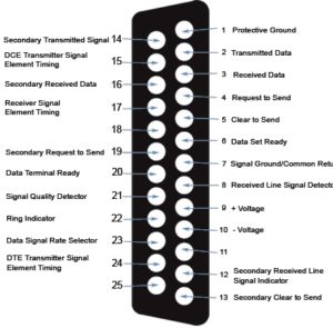
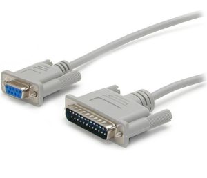
Signal lines: there are 25 pins defined in the RS-232 standard and the connector used with it, called a DB-25 connector, Figure 2a and 2b. Most installations do not need the full 25-pin set, so subsets with 15 pins (DB-15) and even 9 pins (DB-9) were commonly used; some proprietary systems used a non-standard connector. The 25 pins include the data lines and control lines which manage the link’s operating status and implement back-and-forth handshaking. The most important of these lines are Request to Send (RTS), Clear to Send (CTS), Data Set Ready (DSR), and Data Terminal Ready (DTR).
Fig 2: a) The full RS-232 standard calls for a 25-pin connector and associated signal lines (Source: Black Box Network Services) ; b) (below) the physical connector is very large by today’s perspective, and smaller connectors such a the 9-in version, were also used in some cases (Source: StarTech.com)
All lines are “single ended” which means their voltages are measured with respect to a ground wire in the cable. This single-ended signal and ground become a source of problems over long distances due to voltage drop across the ground wire and poise pickup within the ground wire.
Signal and bit timing: These are asynchronous standards, which means there is no common clock between sender and receiver, nor does the receiver try to extract a timing clock from the received data stream. The standard supports many data rates, including 110, 300, 600, 1200, 2400, 4800, 9600, 14400, and 19200 baud (a baud is usually, but not always, the same as a bit/second). The DTE and DCE must be set to the same baud value. Many “sort-of” RS-232 systems support higher baud rates, but they are staying within the definitions of the standard and so may be incompatible with other units.
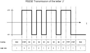
The bit timing is simple and complicated at the same time. When there is no data to transmit, the data line is in “mark” state, also called the idle state. When there is data to send, the line goes to the space state for one bit-period to generate what called the start bit. This alerts the other end of the link to wake up and be ready to receive bits. The start bit is followed by between five and eight data bits, depending on the setup of the system (seven and eight data bits are most common variations). The LSB is sent first, and the MSB is sent last.
After the data bits comes the stop-bit sequence, which consists of sending the marking state for 1, 1 ½, or 2 bit-periods, again depending on the system set-up. The standard allows the user to insert a parity bit (choice of odd or even parity) after the last data bit but before the stop bit, to provide a modest level of error detection, Figure 3.
Fig 3: This transmission of the letter J using ASCII encoding shows the transition from idle mode to start bit followed by 8 data bits, one parity bit, one stop bit, and the return to idle mode.(Source: Electro-Tech-Online)
Part 2 will continue the explanation of RS-232, along with some extensions to the standard and test issues.



Leave a Reply
You must be logged in to post a comment.