Brushless DC and stepper motors may get more attention than the classic brushed DC motor, but the latter may still be a better choice in some applications.
Most designers looking to choose a small DC motor – a sub- or fractional-horsepower unit, typically – usually look initially at just two options: the brushless DC (BLDC) motor or the stepper motor. Which one to select is based on the application, as the BDLC is generally better for continuous motion while the stepper motor is a better fit for positioning, back-and-forth, and stop/start motion. Each motor type can deliver the needed performance with the right controller, which can be an IC or module depending on motor size and specifics. These motors can be driven with the “smarts” embedded in dedicated motion-control ICs or a processor with embedded firmware.
But look a little closer at the offerings of the vendors of these BLDC motors, and you’ll see they almost always also offer brushed DC (BDC) motors, which have been around “forever.” This motor arrangement has a long and established place in the history of electrically driven motive power, as it was the first electric motor design of any kind. Tens of millions of these brushed motors are used every year for serious, non-trivial applications such as cars.
The first crude versions of brushed motors were devised in the early 1800s but powering even a small useful motor was challenging. The generators needed to power them had not yet been developed, and the available batteries had limited capacity, large size, and still had to be “replenished” somehow. Eventually, these problems were overcome. By the late 1800s, brushed DC motors ranging into the tens and hundreds of horsepower were installed and in general use; many are still used today.
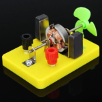
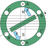
The basic brushed DC motor requires no “electronics” to function, as it is a self-commutating device. The principle of operation is simple, which is one of its virtues. The brushed DC motor uses mechanical commutation to switch the polarity of the rotor’s magnetic field (also called the armature) versus the stator. In contrast, the stator’s magnetic field is developed by either electromagnetic coils (historically) or modern, powerful permanent magnets (for many present-day implementations) (Figure 1).
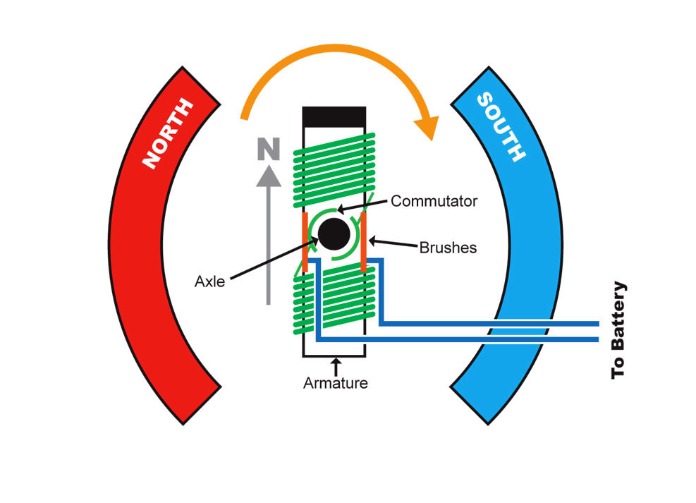
The interaction and repeating reversal of the magnetic field between rotor coils on the armature and fixed field of the stator induce the continuous rotary motion. The commutation action that reverses the rotor field is accomplished via physical contacts (called brushes), which touch and bring power to the armature coils. The motor’s rotation not only provides the desired mechanical motion but also the switching of the rotor coil polarity needed to induce the attraction/repulsion with respect to the fixed stator field – again, no electronics are needed, as the DC supply is applied directly to the stator coil windings (if any) and the brushes.
Basic speed control is accomplished by adjusting the applied voltage, but this points to one of the shortcomings of the brushed motor: the lower voltage reduces the speed (which was the intention) and dramatically reduces the torque, which is usually an undesired consequence. Using a brushed motor powered directly from the DC rails is generally acceptable only in limited or non-critical applications such as operating small toys and animated displays, especially if speed control is needed.
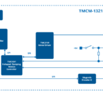
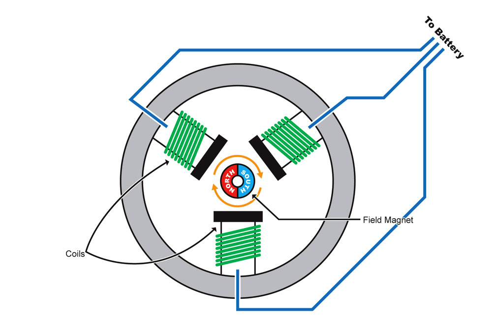
In contrast, the brushless motor has an array of electromagnetic coils (poles) fixed in place around the housing interior, and high-strength permanent magnets are attached to the rotating shaft (the rotor) (Figure 2). As the poles are energized in sequence by the control electronics (electronic commutation – EC), the magnetic field surrounding the rotor rotates and so attracts/repels the rotor with its fixed magnets, which is compelled to follow the field.
The current driving the BLDC motor poles can be a square wave, but that’s inefficient and induces vibration, so most designs use a ramping waveform with a shape tailored for the desired combination of electrical efficiency and motion precision. Further, the controller can fine-tune the energizing waveform for fast yet smooth starts and stops without overshoot and crisp response to mechanical load transients. Different control profiles and trajectories are available that match motor position and velocity to the application’s needs.
The next part of this article looks in more detail about where and why the brushed DC motor is still a legitimate choice to consider, despite its known shortcomings.
Related EE World Content
- Driving brushed and brushless DC motors
- Speed Controller for Brushed and Brushless DC Motors
- Brushed DC Motors in Industrial Versions
- Basics of motion-control profiles, Part 1: Context
- Basics of motion-control profiles, Part 2: Ramp profiles
- Basics of motion-control profiles, Part 3: Implementations
- Motor fundamentals and DC motors
References
Machine Design, “Controlling Brushed DC Motors Using PWM”
Medical Design Briefs, “Every Drop Counts: Designing Motors to Optimize Home and Ambulatory Infusion Pumps”
Portescap, “Miniature Motors Deliver Big Performance for Medical Analyzers”
Portescap, “Selecting Miniature Motors for your Medical Devices”
Portescap, “Brush DC Motor Basics”
Portescap, “Controlling Brushed DC Motors Using PWM – Optimal Frequency, Current Ripple and Life Considerations”
Toshiba, TB9053FTG and TB9054FTG Data Sheet