The hot wire anemometer for measuring fluid speed offers unique advantages but also has some challenging use issues.
Part 1 looked at the basic principles of the hot wire anemometer. This part contains the discussion with issues related to calibration and practical concerns. As with so many other sensors, the HWA looks simple enough: It has no moving parts, which is good, and its small mass means fast response. However, it requires complicated equations to relate the desired variable of gas flow to the measured current through the heated element or to the resistance of that element (depending on if the CCA or CTA approach is chosen, respectively).
This correlation is actually a multipart process, with two major aspects. First, there needs to be a model of heat convection from the thin wire to the moving gas. These equations are complicated, and also need be adjusted for “edge effects” at the ends of the sensing wire, wire diameter, and other issues, as well as the usual issue of tolerances and sensitivity of readings to them. HWAs are especially useful over the range of about 0.1 meter/sec to 25 meter/sec flow; nominal probe resistance at 25⁰C is usually in the single-digit ohms.
There are also adjustments for gas density, type (different gases have different convection coefficients), temperature, humidity, and other subtle factors. Rather than repeat the analysis, the references below go through it at both a higher-level with some simplifications as well as with fully detailed discussion.
Calibration is also an issue. The modeling may be good, but it’s is still a model which approximates reality. Therefore, use of an HWA requires calibration for several major areas:
- What is the actual, not just theoretical, relationship between the flow velocity and the actual sensor resistance for the gas being measured? Even after this situation is fully modeled and the relationship characterized, there are assumptions and approximations that must be checked.
- What is the relationship between change in resistance of the wire and is the relationship to temperature? The temperature coefficient of the wire as a sensor is not linear, and this non-nonlinearity must be modeled as well.
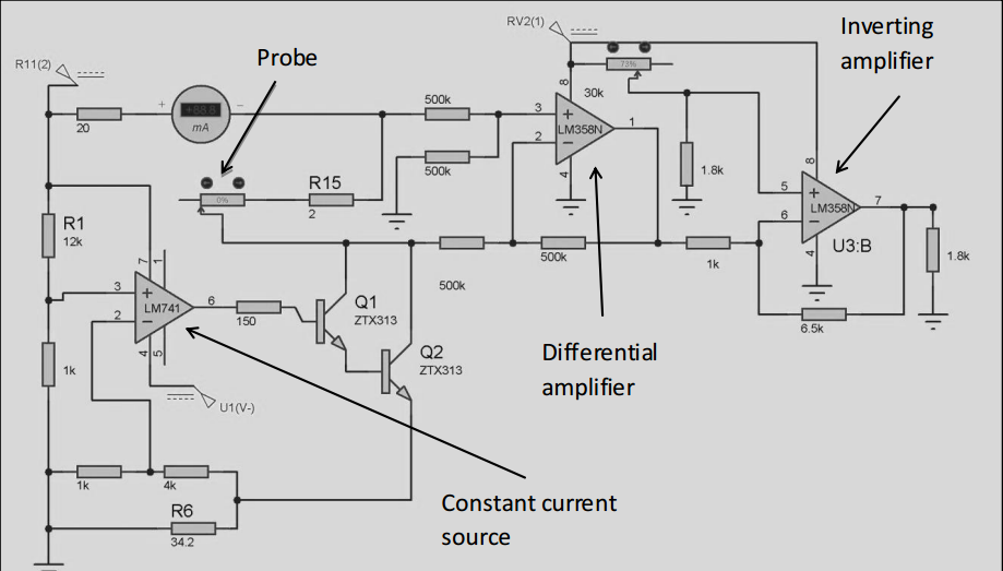
- Finally, the system needs end-to-end calibration to account for electronics offsets and other errors. Using an HWA for approximate measurements, to 2 to 5% accuracy, is not difficult, but using it to read to better than 1% requires extra planning, analysis, and attention to details. With today’s electronics, the basic interface is not difficult to build; (Figure 1) is a representative schematic of the needed analog circuitry.
History of the HWA
Much of the history of the development of the HWA is “blurry” but the first serious work started at the beginning of the 20th century before the “electronics” needed even existed. Decades before that, physicists worked out the theory of convection from heated objects decades as part of their fluid flow and thermal investigations.
The initial HWA effort and research focused on verifying those equations and convection cooling of heated objects such as wires. The second stage was to develop circuits which could provide CCA and CTA implementations, using manual control and galvanometers, to investigate and better understand the relationship between flow rate, sensor current, sensor resistance, and temperature.
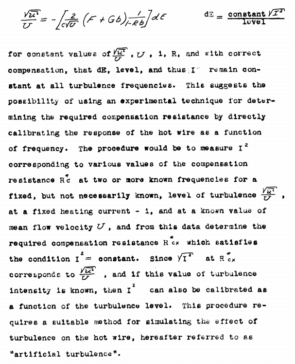
Interestingly, much of the review of the historical development, and the effort that “pulled together” the multiple stages of research, was done at the California Institute of Teycbnnlgy (Cal Tech) and presented in 1939 Ph.D. thesis by Frederick Delbridge Knoblock. Perhaps somewhat amazing, his entire 144-page thesis is posted on the web as a scanned document, “Investigations of the Application of the Hot Wire Anemometer for Turbulence Measurements” (see Reference). Reading it – and it is readable even with the advanced math and partial differential equations – is a testament to the level and sophistication of work and reports that were done pre-computer and pre-word processing, as all the equations and Greek characters are written in by hand, (Figure 2).
Pros and cons of the HWA
The HWA is not easy to use, both physically and in terms of collecting meaningful data, but it offers some distinct advantages. Among them:
- The associated electronics (current source, op amps) are relatively inexpensive and accurate.
- The small element has wideband response, which is good for measurement of turbulent flow.
- The small size interferes minimally with gas flow (but it still can).
- It can operate in high-temperature flows such as exhausts, within the limits of the sensing element and its insulating supports.
- It can be used with a wide variety of gases and liquids, including those which are electrically conductive, transparent, or opaque.
At the same time, the HWA has drawbacks and areas where it may not be a good fit:
- The probe assembly can induce turbulence, depending on the size of the “pipe” versus the sensor.
- The problem can be contaminated or get clogged.
- The probe is generally very fragile and must be handled and installed with great care.
- The support which hold the wire act as heat sinks for the sensor wire and can affect accuracy, so the entire assembly must be calibrated, and then the results adjusted accordingly.
- The probe wire must be oriented at right angles to the flow; if the flow direction changes, the results will be affected (special two- and even three-dimensional probes are available but with more complexity, fragility, and cost).
So many probe arrangements
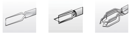
It’s easy to assume that a single pair of supports, with a tiny wire stretched between them, constitutes the probe, end of story. That’s the situation in many cases, but specialized applications use different probe configurations. The probe wire material must have a high-temperature coefficient of resistance, and can be platinum, tungsten, platinum-iridium, or other metals; it can also be some plated wire.
The probe needs mechanical strength so that it may have a quartz backing. The length of a wire-based probe typically ranges from 1 to 3 mm with a wire diameter of around 5 μm but can range from 1 to 10 μm. Also, the probe can actually be constructed as a thin film deposited on a substrate for more strength but with increased flow impediment. Even if a wire is used, the arrangement can be varied to accommodate advanced tests needing two and even three-dimensional measurements, (Figure 3).
Conclusion
The hot wire anemometer is an effective flow-velocity measurement arrangement capable of high accuracy with minimal interference in the fluid path. However, it also requires great care in probe arrangement and calibration as well as system calibration, understanding of flow rate versus electrical signal, sources of error, and more.
Although there are alternatives to the HWA, there is no single “best” measurement technique for all applications. For this reason, other approaches such as laser Doppler or ultrasonic flow measurement may be a better choice in a given situation. However, the challenges of using the HWA may be reduced somewhat through the use of MEMS based approaches. Here, the entire probe assembly is fabricated on a silicon-based substrate, with a nanometer-sized probe along with some signal-conditioning circuitry, see References.
EE World References
- The working principle, applications and limitations of ultrasonic sensors
- Temperature Sensors: thermocouple vs. RTD vs. thermistor vs. semiconductor IC
- Precision-resistor devices simplify thermal sensing
- What are cryogenic temperature measurements? Part 2
- What are cryogenic temperature measurements? Part 1
- How can you get digital temperature data?
- Coriolis flowmeters, Part 2: The principle
- Coriolis flowmeters: A subtle global effect with local applications, Part 1: The challenge
- How do you calculate flow from a pressure measurement?
External References
HWA Operation and Analysis
- Science Direct, Hot wire anemometer
- Electronic Journal of Fluids Engineering, Transactions of the ASME, “Review of Hot-Wire Anemometry Techniques and the Range of their Applicability for Various Flows”
- Instrumentation Tools, “Hot Wire Anemometer Principle”
- Circuit Globe, “Hot Wire Anemometer”
- Virginia Polytechnic Institute and State University “Hot-Wire and Hot-Film Anemometry”
- University of Leicester, “Hot-wire anemometer calibration”
- Journal of Physics, “Calibration method for a hot wire anemometer”
- Middle East Technical University (METU) OpenCourseWare, “Hot Wire Measurements“
- Wikipedia, “Anemometer”
- Budapest University of Technology and Economics, “Hot-Wire Anemometry”
- Electronic Journal of Fluids Engineering, Transactions of the ASME, “Review of Hot-Wire Anemometry Techniques and the Range of their Applicability for Various Flows”
- Jove, “Hot Wire Anemometry”
- University of Cambridge, “Hot-Wire Anemometers”
- com, “Hot Wire Anemometer”
- University of Virginia, “How to use the Dantec hotwire anemometer”
- Advanced Thermal Solutions, “Understanding Hot-Wire Anemometry”
HWA History
- Annual Review of Fluid Mechanics, “Hot Wire Anemometry”
- Frederick Delbridge Knoblock, “Investigations of the Application of the Hot Wire Anemometer for Turbulence Measurements” (Caltech 1939)
MEMS-based HWAs
- Journal of Physics, “A novel design and analysis of a MEMS ceramic hot-wire anemometer for high temperature applications” (2006)
- Conference: Design, Automation and Test in Europe, “Hot Wire Anemometric MEMS Sensor for Water Flow Monitoring” (2008)
- Micromachines, “Micromachined Thermal Flow Sensors—A Review” (2012)
- Griffith University, “MEMS Anemometer” (2007)