I have mentioned Fourier transforms in other posts but it is probably worthwhile explaining more about Fourier transforms in order to show why I think they are so important to analog signal processing. You may come across several theorems containing the name “Fourier” such as the Fourier Series, Fourier Transform, Fourier Integral and Fourier Analysis. When used in relation to electronics, they are all relating to the same theorem. As an analog design engineer, I am only really interested in theorems when I can see a relevance and use in design. So, while I can look up the theory of the Fourier Series, I need to know the relevance to electronics design. Otherwise, it is just math.
The Fourier series is a way of representing any periodic waveform as the sum of a sine and cosine waves plus a constant. A good starting point for understanding the relevance of the Fourier series is to look up the math and analyze a square wave. You will find that a square wave can be made from an infinite number of odd harmonic sine waves of progressively reducing amplitude. So, for a 100Hz square wave, you would need to add together a 100Hz sine wave as well as 300Hz, 500Hz, 700Hz etc. The magnitude of the harmonic components will be 1/3 of the 100Hz amplitude for the 300Hz, 1/5 for the 500Hz, 1/7 for the 700Hz etc. You need an infinite number of harmonics to produce a perfect square wave and quite a lot of harmonics to get close to a square wave.
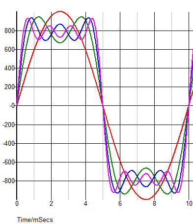
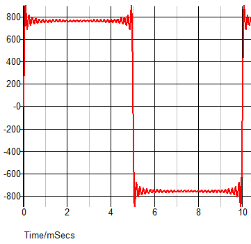
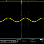
The example above shows what happens if you start with 100Hz sine wave (red trace) then add in the right proportion of 300Hz (green trace), then add 500Hz as well (blue trace) and finally 700Hz (cyan trace). While the waveform is now looking a lot less like a sine wave it is a long way from a perfect square wave. Even with 32 frequencies (i.e. 100Hz up to 6300Hz components), the waveform is still noticeably imperfect.
However, this is a mathematical exercise. You are unlikely to try making a square wave that way – square waves are very easy to generate! The reason for the interest in Fourier Series is because you can use it to understand what a square wave (or any non-sine wave) is like to process in analog electronics. If you have a square wave, even of a low frequency, and need to amplify it or perform some other analog signal processing to it, you can see that if you don’t have an infinite bandwidth you will lose the higher order harmonics and the square wave won’t be a square wave any more.
This isn’t always as disastrous as you might think. The effect of losing the higher frequency components from a square wave is to lose some of speed of the rising and falling edges. However, if you also start to introduce different delays to different frequencies (which is quite likely) then things can get messy.
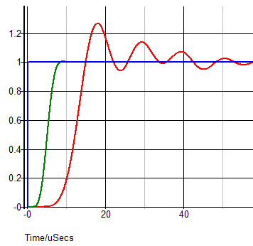
This shows the edge of a square wave with a fast rising edge (blue trace) and the effect of a high order Bessel filter (green trace) with a cut-off frequency 100 times the frequency of the square wave. You would expect it to have little effect other than slowing the edge down, and that is exactly what it does. There is a very small overshoot on the green trace. As you may know, the Bessel filter is the best type for preserving group delay and hence controlling the phase shifts that could otherwise be problematical to preserving waveform shape. The red trace shows what happens when you don’t preserve the phase – using a high order Chebyshev filter instead of a Bessel. As you can see there is a massive overshoot and ringing, and a slower rise time.
So, without actually doing any math you can hopefully understand that if any periodic non-sinusoidal waveform can be represented by an infinite number of sine/cosine waves of specific amplitudes if you do anything to alter those amplitudes or their phase, you will alter the shape of your initial waveform.
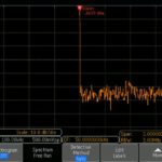
You can also look at your waveforms in the frequency domain. While that is useful (or essential) in some areas of electronics, for the purposes I am describing here it is of limited use. Looking at a waveform on a spectrum analyzer or doing an FFT (Fast Fourier Transform) may help you understand how high the frequency components of a waveform are but it won’t tell you which ones are the most significant. A simulation of the proposed signal processing is an easier way to determine the effect on your waveform.

Leave a Reply
You must be logged in to post a comment.