The thermal printer is an alternative to inkjet and laser printers and has a significant place in application niches for which it is especially well suited.
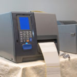
Thus far, we have looked at thermal printers’ basic operating principles and attributes. This section looks at the components and circuitry of a complete direct-printing unit. A typical small ticket or receipt thermal printer using the direct approach has a resolution of 8 dots/mm (200 dpi) with a line width of 48 mm for a total of 384 dots/line.
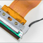
A thermal printer module is the printer’s core (Figure 1) and contains the heating elements that will initiate the darkening of the thermally sensitive paper.
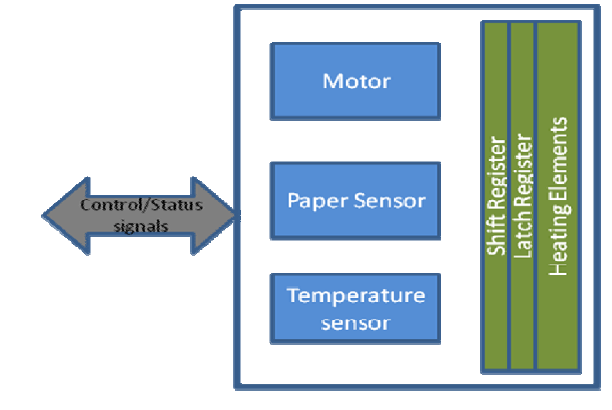
It is not electrically practical to have individual power drivers for each heating element (384 in this case). Instead, a multiplexing arrangement is used where the heating elements are controlled in groups of eight (Figure 2).

A shift register is used to send a string of bits with a 1 indicating the element needs to be turned on while a means it should be left unpowered. A strobe signal is used to actually apply power to the elements in groups. The length of time for which power must be applied is a function of the head design, available current, and thermal mass. Applying power for too short a time means the thermal and darkening action will be incomplete; for too long, the paper will darken in a large area around the dot and bleed into adjacent dots. Some thermal printers even include a temperature sensor to monitor the heating, which adds to the cost.
Thus far, the printer has only darkened one row of the paper. A complete printer needs other functions such as advancing the paper to print the entire length and a knife-edge to cut it. A stepper motor is well suited for this paper-advance/cut action, and it is usually controlled via an H-bridge driving around 1 A to the motor. The thermal heads are usually heated to about 90°C, and typical print times between 5 msec and 20 msec per line; there are always tradeoffs involving power, control, and other factors.
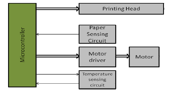
It’s also important for the printer unit to sense if there is paper to be printed on between the roller and thermal head or if the unit is out of paper. This is done using a simple paper sensor using a basic reflective photosensor mounted alongside the thermal-print head. A microcontroller manages the printer and checks to make sure paper is available, all internal functions are ready and controls the printhead driver and the motor. It also interfaces to some basic switches for the user (on/off, paper advance) as well as some basic indicator LEDs (unit ready, fault) (Figure 3).
More-expensive units may have an LCD screen with messages for the user and also functions as a touch screen for the operator to entire some parameters, but basic, low-end printers do not need these. Depending on the installation, the unit may support different system interfaces such as a USB port or UART; wireless units are also now available.
While the printer can be built using about half a dozen medium-scale ICs, the volume of these printers and the relative lack of complexity for their electronic circuitry means that a dedicated system-on-chip (SoC) is the preferred solution in terms of cost, power, and size. This works because digital processing demands that the analog I/O requirements (comparators, drivers, phototransistor interface, temperature-sensor interface, motor control) are modest.
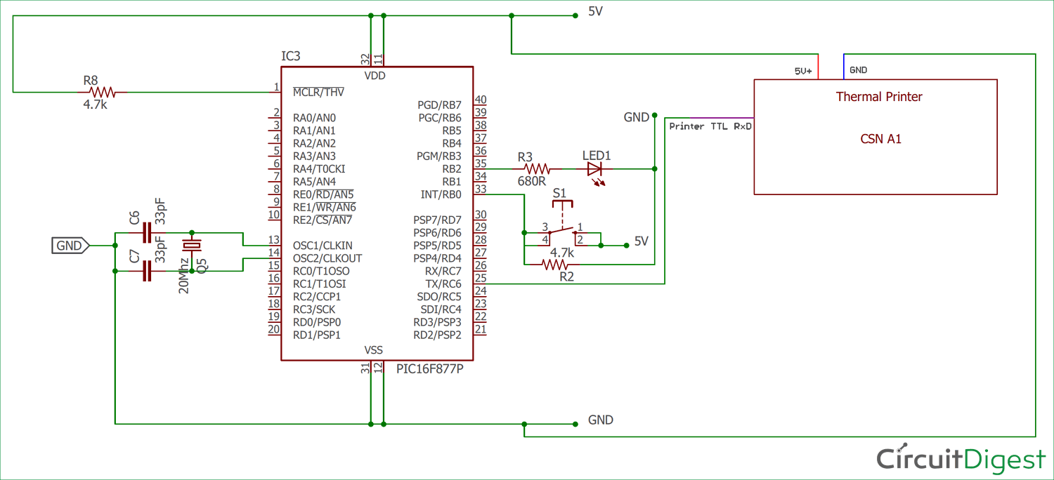
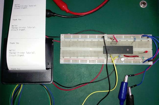
Some printers use a standard 120/240 VAC line and have an internal power supply, while others are battery-powered; some use a USB port for both data and power. In the non-AC version, the low DC voltage is often stepped up via an internal DC/DC boost converter to 24 VDC to increase the thermal head voltage for improved efficiency. Hobbyists have built complete thermal printers using off-the-shelf parts, including a printer module, a PIC16F877A microcontroller, and a few standard discrete components (Figure 4) and (Figure 5).
Conclusion
While the thermal printer is not as well-known as the inkjet or laser printer, it is a valuable addition to the list of printing-technology options. The direct-thermal printer is a low-cost, reliable, easy-to-maintain unit well suited to retail, point of sale, and ticketing settings. At the same time, the thermal transfer approach provides a way to print-rich, lush, long-lasting colors images on almost any flexible medium.
Related EE World Articles
Barcode Printers and Scanners Make Serialization Flexible and Efficient
Portable Wire-Marking, Barcode, And General-Identification Printer
Panel-Mount Printer Unit Reduces Integration Time And Cost
Fujitsu’s New POS Printer is Ultra-Compact and Cost-Efficient
References
- Global Market Insights Inc., “Thermal Printing Market Size“
- Future Market Insights, “Thermal Printing Market“
- Graphics Products, “Thermal Printers vs. Inkjet Printers: Which Printer Should You Choose?“
- Wikipedia, “Thermal printing“
- S. Patent 3,496,333, “Thermal Printer“
- CDW, “How Does a Thermal Printer Work?“
- How-To Geek, “Printing Without Ink or Toner? How Thermal Printers Work“
- VentureBeat, “Best Thermal printer 2021 – 7 Thermal printers Reviews“
- Brother Mobile Solutions, “Direct Thermal vs. Thermal Transfer – Which Print Technology Works Best?“
- Peak Technologies, “What is Thermal Transfer Printing?“
- Science Direct, “Thermal Printers“
- Xerox, “VersaLink® C500“
- Xerox, “PHASER 850 Color Printer“
- Texas Instruments, “POS Printers“
- Cypress Semiconductor Corp., “Developing highly-integrated thermal printer-based applications“
- Circuit Digest (India), “Thermal Printer interfacing with PIC16F877A“
- Visuality (Poland), “Thermal Printer Protocols for Image and Text“


Leave a Reply
You must be logged in to post a comment.