When discussing total harmonic distortion (THD), the fundamental of the wave in question is known as the first harmonic. Quantifying THD, therefore, begins with the second harmonic. Theoretically, the number of harmonics is limited only by some maximum frequency based on minimum quantum wavelength. In reality, however, we are interested in a relatively small number of harmonics because they diminish in amplitude with spectral distance from the fundamental, eventually becoming negligible.
Harmonic distortion is generally undesirable in audio systems as well as other applications where an exact representation of a waveform is important. Another application of THD is in electrochemical systems such as fuel cells where it is used as a measure of linearity over small portions of the cell impedance curve.
THD is generated in non-linear amplifiers, loudspeakers, microphones and other components. In radio communications, additional problems are caused by interference. In power systems, THD manifests as clipping, heating, emissions and core loss in motors, leading to reduced power and shortened life. These harmonics are generated in variable-frequency drives (VFDs).
In audio reproduction, particularly music programming, there is a large amount of intentional harmonic content. That is what distinguishes the great variety of musical instruments. Without harmonics, everything would sound like a collection of tuning forks. (A pure sine wave at high volume is painful to hear because all the power is at a single frequency.) In measuring THD, the intention is not to include these harmonics, but to measure others that are added later in the course of non-linear processing.
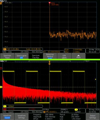
Top, the frequency domain view of a sine wave with a single spike at the fundamental frequency. Bottom, frequency domain view of a square wave (superimposed) with its frequency content extending out to infinity.
To measure the THD contributed in an amplifier, for example, it is necessary to unhook the antenna or CD player and apply at the input a pure sine wave. (Separate measurements can be made at different frequencies.) To find the THD, the output power is measured. Then it is fed through a bandpass filter that eliminates the fundamental, and it is measured a second time. These two measurements provide the information for calculating the THD that pertains to that amplifier.
THD is defined as the amount of harmonic distortion present in a signal. It is the ratio of the sum of the powers of all harmonic components to the power of the fundamental. The method of finding THD by first filtering out the first harmonic actually yields THD + noise. The noise is caused by thermal
motion of charge carriers in conductors, including active and passive components that are part of the equipment under investigation. While noise is not a form of harmonic distortion, it has the same general effect of degrading performance, so it is generally included in the metric.
Disregarding noise for now, the relevant equation is:

where Vx is the RMS voltage of the Xth harmonic.
THD is generally expressed as a percentage of dB relative to the first harmonic. In measuring THD, it is necessary to specify the bandwidth of the measurement. Ground-loop power-line hum, high-frequency interference, intermodulation distortion due to interaction with the first harmonic and similar phenomena are factors.

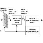
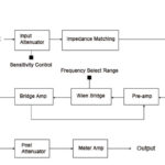
Function blocks of a THD analyzer and its distinctive notch filtering at the fundamental.
A THD analyzer is often the tool of choice for performing these measurements. There are several types of THD analyzers. The most widely used version employs fundamental suppression. The THD fundamental suppression analyzer consists of input matching circuitry, a notch filter and amplifier in the input section, and metering circuitry in the output section. The bridge amplifier and pre-amplifier are connected to provide negative feedback. The output drives an instrumentation amplifier and analog meter or digital readout.
Other THD meters are the heterodyne type, the tuned circuit type, and the spectrum analyzer, which, like the oscilloscope, can be configured to display THD.

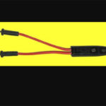
Keithley 2015 Series THD and Audio Analysis Multimeter.
Tektronix offers the Keithley 2015, 2016 and 2016-P Total Harmonic Distortion and Audio Analysis Multimeters with base prices ranging from $5,720 to $6,200. They measure THD over the complete 20 Hz to 20 kHz audio band and can compute THD + noise and signal-to-noise plus distortion (SINAD). The 2015-P and 2016-P directly identify peak values of the frequency spectrum. The 2016 and 2016-P have twice the sine wave generator output compared to the 2015 for applications that require test signals greater than 8 V
RMS.
In addition to processing and displaying the total harmonic distortion content of an electrical signal, the Keithley 2015 THD instrument functions as a conventional bench-type multimeter with enhanced features and capabilities. It makes dc voltage measurements from 0.1 μV to 1,000 V and ac voltage measurements from 0.1 μV to 750 Vpp.
To measure voltage, connect the leads to the HI and LO input terminals. Front or rear inputs can be used. Set the INPUTS button. Then press DCV or ACV. This is an auto-ranging meter, the function activated by pressing AUTO, which displays the AUTO annunciator. To select a manual range, use the UP or DOWN key.
When the leads contact the voltage source to be measured, in manual range overvoltage is indicated if appropriate. AUTOSET can be pressed or successively higher ranges selected until a reading is displayed.
The Model 2015 THD Multimeter can be used to measure electrical current. The dc range is 10 nA to 3 A and the ac range is 1 μA to 3 A RMS.
The hookup for measuring current is similar to the hookup for measuring volts, described above, except that for current measurements, only front panel terminals are to be used. The INPUTS button should be placed in the FRONT position. Then, select DCI or ACI. Auto-ranging or manual ranging can be used. Because in the current mode the meter is in series with the power source, the fuse will blow if greater than 3 A or 250 V is applied.
The Model 2015 THD meter is capable of reading circuit continuity. The one-kilohm range is used.
Connect leads to INPUT HI and INPUT LO. After selecting CONTINUITY, a threshold level from one ohm to one kilohm can be chosen, below which a beep sounds to indicate that the circuit has continuity.
To change the threshold resistance for the continuity function from the ten-ohm default, press SHIFT>CONT. Use the FORWARD and BACK arrow keys to determine a numerical place and use the UP and DOWN keys to set digits from one to a thousand. Press ENTER.
The Keithley Model 2015 THD Analyzer can measure distortion from 0.002% to 100%, which is equivalent to -94 dB to 0 dB. A Fast Fourier Transform (FFT) is performed on the periodic signal at the input. Harmonic levels are measured to calculate THD, THD + noise and SINAD. An internal AFG provides the required sine wave for fundamental suppression. The instrument can limit the harmonics to a user specified number, from default two to 64.
Having quantified the amount of THD, with and without noise, and evaluating the harmful effects that harmonics have, for example in an industrial setting, next on the agenda is devising a plan to reduce or substantially eliminate them.
In an industrial facility, there is usually a wide variety of loads. Relative to power consumed, a large part is comprised of motors. Resistive loads have identical voltage and current loads. This is in contrast to induction motors, which contribute reactive loading to the mix. Still, the current waveform is sinusoidal. Variable frequency drives (VFDs) are valued in today’s world because they permit us to accurately vary the speed and torque of induction motors, previously feasible only in DC motors. A downside, however, is that by means of pulse-width modulation, among other methods, large amounts of power are rectified and the DC reconfigured to create highly non-sinusoidal waveforms with accompanying harmonics. They feed back into the facility branch circuits and even into the utility electrical distribution system.
Shunt filters, which eliminate harmonics on a case-by-case basis, are effective. A single filter cannot be used to eliminate all harmonics. Instead, a separate circuit must be implemented for each of the powerful spikes. A series of oscilloscope displays showing the waveforms as shunt filters are added to reduce harmonics, shows the trace increasingly resembling the original utility sine wave. Other methods for restoring power quality include shielding, cable separation and capacitors installed for power-factor correction.

Leave a Reply
You must be logged in to post a comment.