The solid-state relay may be the first choice, but the venerable electromagnetic relay offers attributes the SSR cannot provide and so may be the best solution.
Everything is solid-state these days, right? Even that one holdover, the vacuum-tube magnetron at the heart of the home microwave oven, is seeing some early signs of competition from cost-effective solid-state power amplifiers. Vacuum-tube amplifiers are used in only some specialty equipment such as high-power transmitters (we’re not looking here at audio enthusiasts who feel tube-amplifier sound technology is better than solid-state; that’s a personal decision).
It’s the same with the solid-state relay (SSR) versus the old electromechanical relay (EMR): the former is now the first relay of choice in most situations and for many legitimate reasons. The function of a relay is conceptually simple: to allow one on/off signal to control the on/off state of another signal line without any electrical contact between them. When you need a relay function, it’s normal to first think of the modern, solid-state version of the classic electromagnetic relay.
The EMR, which is the oldest “electrical” component (thank you, Michael Faraday), functions by energizing a primary-side coil that pulls in an armature, which then causes contacts to close (or open, depending on design) (Figure 1 ). But wait a moment: there are many design situations where the older EMR is still the better or more flexible choice. EMRs fall into three categories: small signal, power, and RF. While their input and output levels, voltages, currents, and frequencies differ, they all have to same operating principle.

In contrast, the SSR input has a photoemitter on the input side and a photodetector on the output side and operates on electro-optic principles rather than electromagnetic ones. Consequently, the input voltage/current is fairly constrained, while the output has some limitations as well.
Despite the many well-known, proven, and impressive virtues of SSRs (no need to repeat them here) and countless tens of millions (maybe billions?) being used in new designs every year, tens of millions of EMRs are also sold each year. While some are for replacement requirements, a significant fraction of these are for totally new design-ins.
What are the attributes of EMRs that keep them going strong? While the EMR is functionally similar to the SSR in the broadest sense, it has many unique characteristics and virtues. Both offer galvanic isolation, but the EMR can do many things which an SSR cannot. Some of the unique attributes and advantages of the EMR include:
- The relay contact forms a basic switch closure, and current through it can be AC or DC, independent of the coil drive; the contact resistance is in the milliohm range, so the voltage drop across the contacts is very close to zero; the open-contact resistance is an air gap and therefore in the multi-megaohm range with near-zero leakage current.
- The EMR is an entirely passive device without active components such as an LED or phototransistor. This has implications for ruggedness and reliability. It is electrically and mechanically robust (partially due to its mechanical and thermal mass) and resists spikes, transients, and EMI, which might momentarily trip or even damage an SSR. Most EMRs are rated for millions of operating cycles, while the sealed reed relay (a type of EMR) has a rating in the tens of millions.
- Despite the metal frame of most relays, neither coil nor contact closure are grounded or connected to circuit common, so the relay can be placed anywhere in a circuit; that can be difficult due to the active nature of the SSR with some circuit topologies.
- While basic relay contacts are normally open (NO) when not energized, there are standard relays with normally closed contacts (NC) when not energized – and many ones that have both, using combined NO/NC contact pairing.
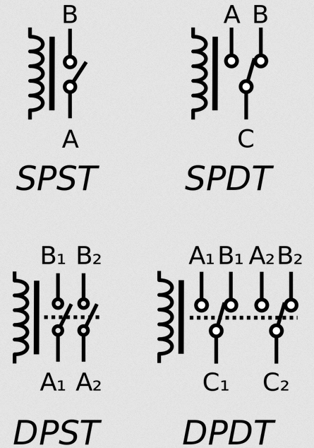
- The relay can be a multipole, multi-contact device with more than one NO or NC contact pair; three, four, or even more independent NO and NC contacts are available, with double-pole/double-throw (DPDT) being the most common (Figure 2).

Fig 2: These are the four most common pole/throw (position) options available in standard electromagnetic relays. (Image source: Wikipedia)
- Even more flexible, these multiple contacts do not have to be carrying the same type and rating of loads, which is another benefit; some contacts can be rated for low-level signals while others can be for power. Where there are a few – just a few – multiple-pole SSRs on the market, they are very limited in scope and ratings.
- Relays can be designed for coil currents as low as 10 or 20 mA or as high as tens of amps, with contacts rated to handling just a few tens of mA and a few volts all the way to several orders of magnitude greater for both parameters.
- EMR contacts are signal “agnostic;” as long as you stay within the voltage and maximum current ratings, it is irrelevant whether it’s a power signal, data signal, or mix across multiple contacts. Further, the load does not have to be well known or defined; it just has to be within the design limits; this is useful in cases where the load may have unknown, uncertain, or hard to control characteristics.
- The most common failure mode of an EMR, by far, is the coil not becoming energized, so a NO contact fails “open” while an NC contact fails “closed” – which one is preferred or necessary may be a safety issue in the application. In contrast, SSRs tend to fail with a short circuit at their output, which may not be acceptable.
- There are standard EMRs available called “latching” relays that maintain their energized contact position even if coil power is removed or fails (a separate coil and signal unlatches them); this is a nice feature in some situations and a vital one in some safety-related ones.
- The relay is very easy to troubleshoot; all that is needed is an ohmmeter to measure the unpowered coil continuity and DC resistance and a simple AC or DC power source to energize the coil.
- Finally, and this is a personal factor for some designers, there’s the viscerally satisfying “click” and observable movement of the armature, which the EMR makes when the relay pulls in or drops out. Some engineers love to hear the “click-click-click”, and even use it to monitor system activity.
Of course, the above reasons do not mean the EMR is “better” than the SSR: they each have their strengths and weaknesses, and SSRs are the better and often only viable choice in many cases.
Personal evidence is just one example
I have many personal situations as a testimony to the usefulness of EMRs. For example, many years ago, I needed to replace a defunct landline phone dialer on a home alarm system. I assumed that the previous dialer and this new one from the same company would be electrically consistent and compatible.
That was not the case. The previous dialer required a transition from high to low to trigger it, while the new one was seeking a transition from ground to “open circuit” as its trigger. Unfortunately, “open circuit” is one of those sometimes-ambiguous circuit terms: does that mean “floating” (truly open), or would disconnecting the line via an open-collector output be sufficient?
Adding to the challenge, the alarm-control unit’s documentation about its output pin was amazingly unclear as to its electrical nature: it might be an open-collector structure, or maybe not. Thus, I could not even say for sure if the control unit’s output was at least potentially electrically compatible with the dialer’s input needs.
What to do? I thought about it for a while and summarized the problem: what I had was an output that went from high to low with unclear structure, and what I wanted instead was for it to look like a dc-signal going from ground to open.
Then, the solution became obvious: use a basic electromechanical relay. I found a DPDT unit with a 12-V, 10-mA coil in my collection. I connected the coil between the supply rail and active output of the control unit and used the relay contacts to connect the input of the dialer to true ground. When the control unit’s output went low (pulled down), it energized the coil, which opened the normally closed relay contacts, and thus provided a true open circuit to the dialer input.
Problem solved…the relay functioned as both a level shifter and signal inverter and gave me absolute electrical (galvanic) isolation as well, so any signal issues at the output of the alarm unit would not damage the input of the dialer.
So, the next time you are faced with a relay requirement, don’t automatically assume you’ll want an SSR. Modern versions of the venerable electromechanical relay – which has been around for about 150 years and is now highly refined and mature – may actually be the right component to solve your problems with the best set of tradeoffs.
EE World Related Content
Solenoids and relays, Part 1
Solenoids and relays, Part 2
High-voltage, long-life dry reed relays rated up to 200 W
Reed relays capable of standing-off 1.5, 2, and 3kVdc
Reed relays capable of switching speeds up to 1 kHz and billions of operations
Goodbye to conventional solid-state relays? MEMS mechanical switches aim to make SSRs a thing of the past
Don’t rush to choose rechargeable batteries…at least, not yet
References
- Doran Scales, “Solid State Relay VS Mechanical Relay – Which One is Best?”
- TE Connectivity, “Electromechanical vs. Solid State Relay Characteristics Comparison”
- Omron, “Difference between SSR and Contact Relay”
- Efficient Plant, “SSR or EMR? Select the Right Relay”
- Happmart, “Introduction to solid state relays and the advantages and disadvantages”
- Crydom, “Why Use Solid State Relays?”
- Iowa State University, “Solid-State Relays for Control” (from 1976 but still makes good points)
- National Control Devices, “Solid State vs Mechanical Relays”
- Automation Technologies Online, “Solid State Relays vs. Electromagnetic Relays”
- Phidgets, “Solid State Relay Primer”
- Glolab Corp., “Relays, The Electromechanical amplifier”
- IEEE Spectrum, “The Resilience of the Reed Relay”


