Part 1 of this article established the context of the problem and why it had defied solution for so long. Once electric locomotives became a viable source of motive power, the tunnel project moved ahead with astonishing speed.
The tunnel defies the critics
Critics said it couldn’t be done, and they had reason to say so. Another tunnel attempt nearby had been abandoned about ten years earlier, mostly due to problems with the unstable silt riverbed. Others said that there was no tunnel structure that could withstand hundreds of 700-ton trains going through every day. The tunnel would distort and fracture from the vibration and stress as they flexed in the soft river bottom, or they just would bend and split under the loads.
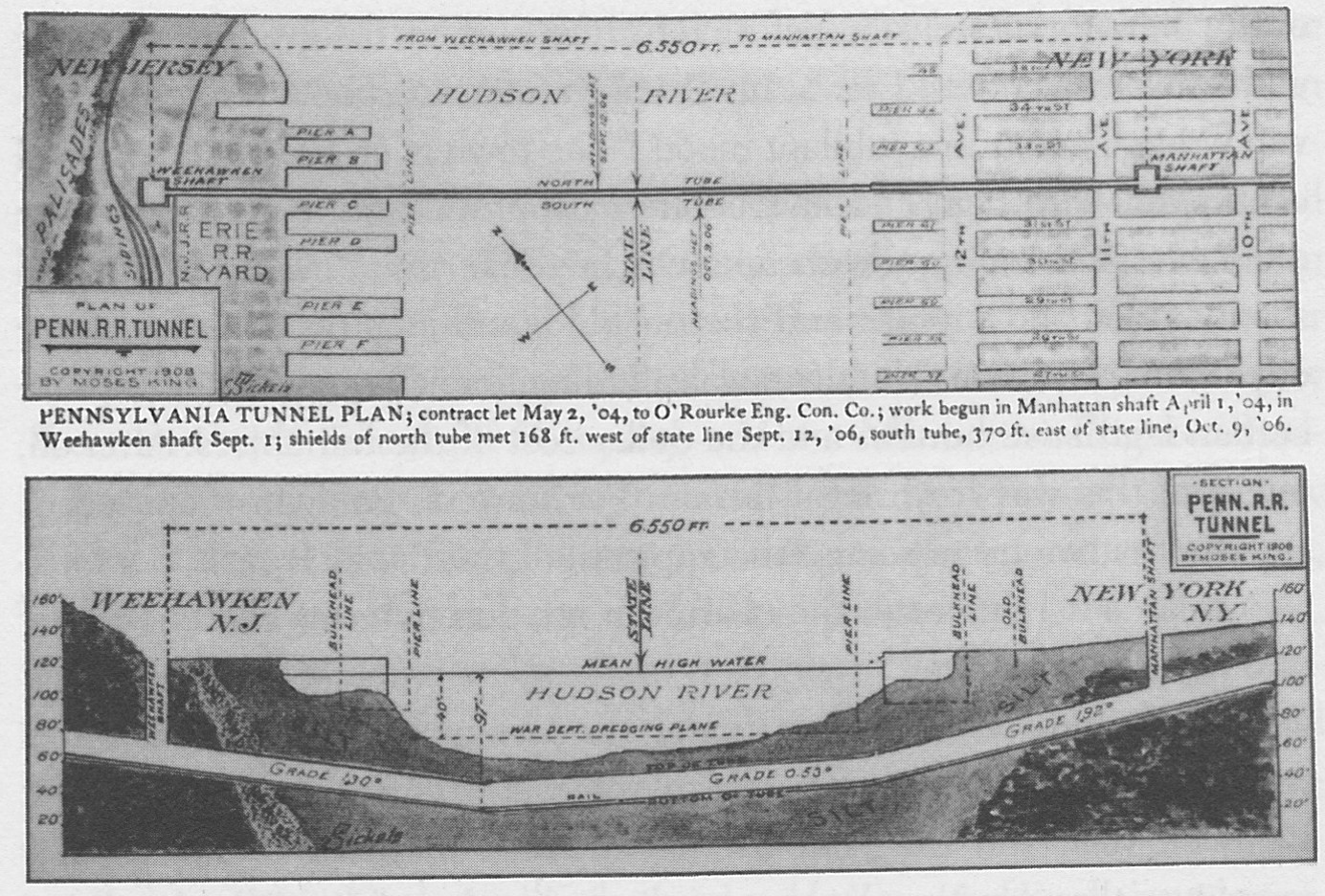
None of this stopped Cassatt and his team. On June 24, 1903, men and machines began digging two holes 30 feet across and 55 feet deep, one on the New Jersey side and one on the Manhattan side. Instead of a single larger-diameter tunnel, there would be 23-foot diameter parallel tunnels; both would be started from each side of the river to meet in the middle. The use of dual tunnels was done for several reasons: to reduce the diameter needed for each tunnel, and to prevent tunnel blockages or crashes if a train derailed. Further, if one tunnel was dedicated for eastbound use only and the other for westbound, the only way there could be a collision was if a train was stopped and the train behind it was not aware of this—and that was preventable with basic signaling.
Digging was done mostly by hand. Thousands of men called sandhogs (and it was all men) worked 24/7 under the riverbed with pneumatic drills as needed, but using hand shovels to scoop away the debris. This debris was put into carts, which were pushed back to the down-hole, where they were raised, then taken away by small, powerful locomotives pulling small hopper cars on specially laid tracks. Doing this work by hand is almost unimaginable. We now have huge tunnel-boring machines that can make slow and steady progress in most cases (but not in all: there was a 57-foot diameter machine broken and stuck under Seattle for over a year (References 3 and 4).
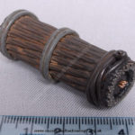
The push forward was slow, and progress was certainly not steady. The tunnel-boring machine at the face of the digging on each side was the “shield,” a 200-ton, 17-foot long, 23-foot diameter mechanical mole with nine doors (Figure 1). One door at a time would be opened, a man would shovel some of the exposed silt and muck into the open work area, the door would be closed, and then another one opened for more extraction and shoveling. When all doors were done, a hydraulic ram would push the face of the shield forward into the cleaned-out area ahead of the shield.

When the push had advanced a few feet, men would bolt a dozen cast-iron segments, each 2 ½ feet wide, to form a ring at the newly opened area at the back-end of the machine, and so another section of the tube was completed. Assembling and bolting the ring segments initially took six hours. As the process was improved, it could take as little as 90 minutes. Progress was between two and three feet per day, but there were many periods when no work could be done due to major technical problems.
To keep the river and silt from coming in when each door was opened, huge compressors on the surface pumped air at about 20-30 psi into the tunnel. Decompression sickness, also known as the “bends”, was a constant danger despite special acclimation zones and airlocks built into the tunnel entrances, and many workers lost their lives to this pressure-related affliction. There were also many blowouts where the compressed air punched through a weakness in the muck, resulting in huge jets of air shooting to the surface, sometimes taking workers with them. Other leaks, blowouts, and floods took hundreds of lives. That was a very different period in worker safety.
Tunnel alignment was a major issue, of course, and there were no laser-based surveying instruments, GPS locators, computers for extensive calculations, and all the other standard tools of today’s surveying metrology. A team of over a dozen men was responsible for making precise measurements of each tunnel as it advanced, and relaying their data to the surface. A 60-foot high tower was built on the New Jersey side as a zero-point of reference for the complex surveying triangulation needed to assess both the vertical and horizontal alignment as each section was added. As the team determined the inevitable deviations via complex sets of measurements, they would relay instructions to the tunnel crew to adjust the trim of each newly bolted-on ring section via tiny shims. The entire measurement and adjustment process could take hours for each ring.
Despite many technical challenges and setbacks, the two sides of the north tunnel met and punched through on Sept 11, 1906, 97 feet below high tide. Then came the moment of truth: how close to perfect alignment were the tubes as they met? A test sighting was performed through a small hole at the meeting junction, and the misalignment at the mid-point was only between 1/16 and 1/8 inch, truly an impressive and astounding accomplishment in surveying. Based on this match, the workers completed digging through, and the north tunnel core was done.
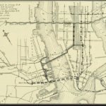
The north tunnel was done a year ahead of schedule; the south tunnel was connected a month later with similar accuracy. There was still much electrical work to be done, track to be laid, and much more, but the basic tunnel was ready (Figure 2). On September 12, 1906, management of the PRR and its engineering team did what most said was impossible: they walked under the Hudson River from New Jersey to Manhattan. The public acclaim was similar to the moon landings. Cassatt suddenly died on December 28, 1906 of a heart attack — the fifth president of the PRR to die while on the job.
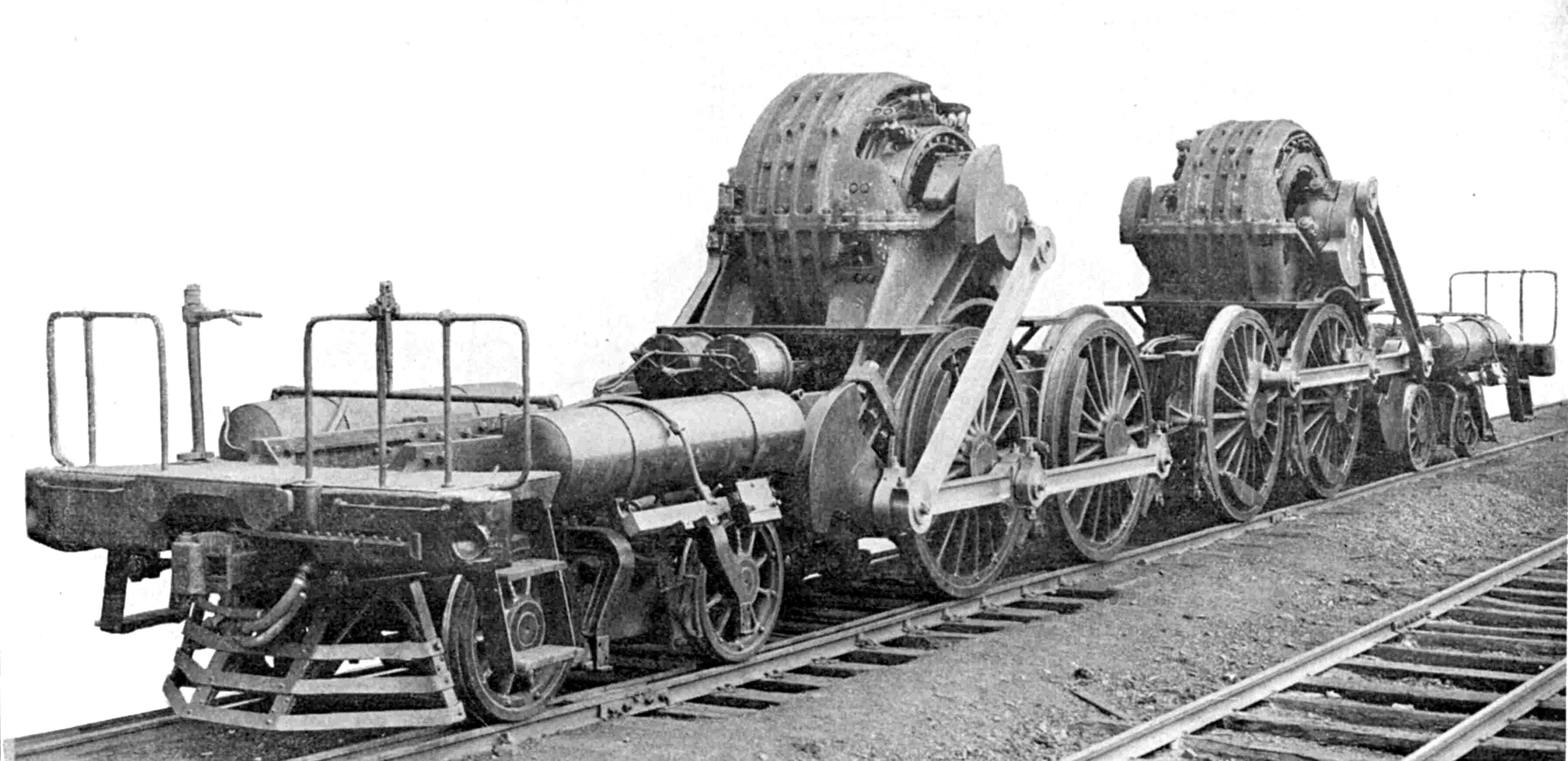
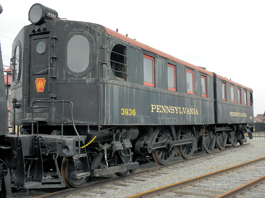
Custom-designed DD1 locomotives (Figure 3a and 3b), (650 V DC, about 1500 horsepower) from Westinghouse and Baldwin Locomotive Works were used. These DC-powered units used a third rail and could start 850-ton trains up the steep 1.94% grade in the westbound tunnel (References 5 and 6). The double-ended locos (so no need to turn them around) were more powerful than available steam-powered engines, could reach 80 mph, and had an amazingly good reliability record (averaging 1 minute of failure for every 11,500 miles).
Still, there were worries. Even after successful completion — but before any trains passed through — a stream of data from the surveyors showed that both north and south tunnels were moving up and down every day (remember, this was laboriously measured before our “modern” sensors and electronics, or the IoT). The problem was studied for months, with no clear idea why this was happening or if this motion would result in tunnel cracking. Eventually, the cause was uncovered: it was the tidal motion of the Hudson River. As the water flowed in and out with the tide, it would exert pressure on the tunnel tubes. The good news was that the cause was now known; the bad news was that no one knew if this would be a problem. We now do know: the tunnels are still intact and functioning over one hundred years later.
Part 3 looks at the Pennsylvania Station itself, a “place,” which was built to complement the tunnel yet had a short life and sad fate.
References (these are just a few of the hundreds of references available via books and web sites)
- com, “New Hudson River rail tunnels needed so old tunnels can be repaired”
- Washington Post/Bloomberg. “Why a Rail Tunnel Under the Hudson River Is Stuck in Washington”
- Popular Mechanics, “Why Seattle’s Huge Tunnel-Boring Machine Is Still Stuck”
- Bloomberg, “Stuck in Seattle“
- Wikipedia, “Pennsylvania Railroad class DD1”
- Fandom, “Pennsylvania Railroad Class DD1”
- CityLab, “10 Gorgeous, Nostalgic Photos of New York’s Old Penn Station”
- Mashable, “1910-1963: The destruction of Penn Station”
- EE World, “The first undersea transatlantic cable: An audacious project that (eventually) succeeded, Part 1
- EE World, “The first undersea transatlantic cable: An audacious project that (eventually) succeeded, Part 2”
- Wikipedia, “James A. Farley Building”
- American Experience PBS Video, “The Rise and Fall of Penn Station,” 2014
- New York Preservation Archive Project, “Pennsylvania Station”
- Jill Jones, “Conquering Gotham—A Gilded Age Epic: The Construction of Penn Station and Its Tunnels,” Viking, 2007
- Lorraine Diehl, “The Late, Great Pennsylvania Station,” Four Walls Eight Windows, 1996


Leave a Reply
You must be logged in to post a comment.