Unlike better-known electromagnetic motors, the widely used piezoelectric-based motor/actuator provides precise, repeatable linear motion over short distances, and requires a voltage drive rather than a current drive.
Part 1 of this FAQ looked at the moving piezoelectric element of the actuator. Part 2 looks at their drive requirements, which are very different than those of “conventional” motors.
Q: What are the drive requirements for a piezoelectric element?
A: It takes an applied voltage, ranging from 30 V to hundreds and even thousands of volts depending on the crystal size, desired elongation, and other factors.
Q: How does this differ from the drive of a conventional electromagnetic motor, whether AC, DC, brushed DC, or brushless?
A: All of those motors are current-driver actuators. Even though the design engineer may be thinking in terms of applied voltage, it is the current through the coils that the motor “sees” and actually creates the magnetic force, regardless of the drive voltage pushing that current. The ideal motor-drive is a controlled current source, although it can be approximated by a voltage source driving that current.
In contrast, the piezoelectric crystal needs to see an applied voltage, and it is this voltage which determines and drives its action, Figure 1. Of course, there is a current which accompanies a voltage any real time work is done (in the physics sense, as is the case here) but voltage is the controlling parameter. The associated current can be in the range of a few mA to several amps.
Fig 1: This piezo-drive waveform is designed to optimize performance for a specific inkjet-printer printhead. (Image source: Apex Microtechnology)
Q: How do you develop such a drive voltage?
A: At lower voltages, in the tens of volts, standard op amps may be suitable if their process is a higher-voltage one. This works well for small elements such as used in tiny positioning devices (or even piezo-based sounders/buzzers, which are “crude” but effective and widely used). Another option is to use a standard lower-voltage op amp but with voltage-boosting transistors (usually bipolar, sometimes FETs) on their output.
Note that the piezoelectric element looks like a capacitive load (again, in contrast to the inductive load of a motor and its coils) so the voltage driver must be designed for supporting capacitive loads without concern for oscillation or stability issues. This load may range as high as 1000 nF.
Q: Is that all that is needed?
A: No, regardless of the approach used to build the analog high-voltage driver, the driver itself needs a high-voltage DC rail as its supply. Providing this high-voltage supply can be a challenge, as most basic AC/DC or DC/DC converters produce a much lower-voltage rail at up to several tens of voles. Thus, the drive problem has two parts: providing a DC supply of high-enough voltage, and then developing a high-voltage amplifier which operates from this supply to drive the element.
Q: Are those the only driver-design options?
A: No. To meet the need for high-performance voltage drive for the piezoelectric element, there are vendors who offer high-voltage op amps in monolithic and hybrid form which can deliver the voltage (and current) needed and can drive the highly capacitive loads.
Q: Are there any other driver issues?
A: Of course! The piezo element is “floating” (not ground referenced) so the driver must have a differential output with no reference to system ground. This complicates the driver design and topology but is a solvable problem
Q: What about safety? We’re in the higher-voltage regime here, right?
A: Yes, there are safety issues. Once the drive voltage gets above around 50-60 volts (depending on application, region, and regulatory standards) there are issues of user safety, physical isolation, and protection from the voltages, as well as mandates defining minimum creepage and clearance dimensions which are a function of the voltage level. Therefore, it into not just a matter of designing, building, and connecting the high-voltage supply and driver. Instead, the details of the installation must take into consideration regulatory requirements, access barriers, and even electromechanical interlocks.
Q: Do I have to build my own power supply? And my own driver?
A: Of course not. The piezoelectric-based motor market is very large (although largely “invisible”) so there are specialty power-supply vendors who offer high voltage/lower-moderate current supplies for the driver. These units range in size from much smaller than a deck of cards to larger chassis units, and not only meet the electronic requirements but are fully complaint with regulatory mandates (which are complicated and a challenge to understand). The power supply is almost always a “buy” rather than “make” decision.
Q: But what about the drivers?
A: There are standard ICs and modules targeted at piezoelectric devices. Again, designing, building, and certifying these higher-voltage amplifiers is not an easy task, so the tendency is to either go with “buy” or at least with a qualified reference design.
Q: What are some standard piezo-driver products?
A: There are many; here are several:
- The Analog Devices ADA4700-1 is a high-voltage precision amplifier operating to ±50 V. This 8-lead SOIC device is optimized for providing high slew-rate output into capacitive loads as high as 100 nF while remaining stable. The data sheet has over 60 performance graphs across many scenarios to characterize it over a wide variety of operating conditions (voltages, loads, temperatures, distortion levels, and overshoot). If more drive current is needed, an external pair of complementary (PNP/NPN) transistors can be added to boost that level. Figure 2.
Fig 2: If additional output current is needed, a PNP/NPN transistor pair is added to the output of the ADA4700-1. (Image source: Analog Devices)
- Texas Instruments has the DRV8662 piezo haptic driver; it operates from a single 3.0 V to 5.5 V supply yet delivers up to 105-V via its integrated voltage-boost switch. It can drive 100 nF at 200 VPP; 150 nF at 150 VPP, 330 nF at 100 VPP, and 680 nF at 50 VPP and is tiny, packaged in a 20-lead, 4 mm × 4 mm QFN housing.
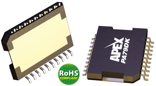
- Apex Microtechnology offers the PA79, a high-voltage (±10 to ±175 V) , high-speed, low-idle current (1 mA) op amp which can deliver up to 200 mA peak-output current, at slew rates over 350 V/μs, It is housed in an electrically isolated 20-pin PSOP package that requires less than one square inch of board space, Figure 3.
Fig 3: The Apex Microtechnology PA79 provides ±10 to ±175 V, up to 200 mA peak-output current, and at slew rates over 350V/μs.(Image source: Apex Microtechnology)
Q: What about reference designs?
A: Due to the wide use of these actuators in some well-defined applications, some vendors offer not only ICs and modules but also complete reference designs.
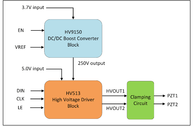
For example, Microchip Technology has a complete design for a piezo-motor fluid micropump with flow charts, code, schematic, layout, the low-voltage power-subsystem for the charger, microcontroller, the high-voltage section which drives the piezo-based pump, and more, Figure 4.
Fig 4: In addition to the conventional low-voltage subsection, the design uses a two-IC approach to boosting and managing the design’s low-voltage rail to the 250-V level needed by the piezo pump. (Image source: Microchip Technology)
The reference design – which has been built and tested — uses their HV9150 DC/DC boost converter and HV913 high-voltage driver. The boost converter transforms the low-voltage rail from the rechargeable battery to 250 V, which is then used to power the driver IC to actuate the piezoelectric micropump.
This FAQ has looked briefly at the piezoelectric-based motor/actuator, a non-obvious and innovative answer to a class of motion problems that would otherwise be difficult to solve. It provides high-speed, precise, accurate motion over a limited range, and with significant force. Unlike the better-known current-driven electromagnetic motors, it is a voltage-drive device and so needs unique drivers which can deliver higher voltages into capacitive loads.
References
- EEWorld, “Basics of AC, DC, and EC electric motors (Part 2) — EC and stepper”
- EEWorld, “Basics of AC, DC, and EC electric motors, Part 1— AC and DC”
- EEWorld, “Piezoelectric sounder puts out 100 dB to alert vehicle drivers”
- EEWorld, “Mechanical vibration for electronics: the quartz crystal”
- Piezo Systems, History of Piezoelectricity
- Analog Devices, ADA4700-1 data sheet
- Texas Instruments, DRV8662 data sheet
- Microchip Technology, AN2014, “Piezoelectric Micropump Driver Reference Design Application Note”
- Apex Microtechnology, PA79 data sheet
- Apex Microtechnology, AN44, Driving Piezoelectric Actuators
- ANSYS Inc, “Multilayer Piezoelectric Actuators: Can a Single Layer be Modeled to Simulate the Layered-stack?”





Leave a Reply
You must be logged in to post a comment.