Part 1 of this FAQ explained the what and why of load-pull tests of RF devices and impedance matching. Part 2 looks at various ways the test can be set up and run.
Q: What’s the basic test setup for a modern load pull?
A: As shown in the figure of Part 1 (and repeated below, Figure 1), the stimulus for the test consists of a controllable RF signal generator, the power sources for the DUT, an amplifier to drive the DUT, and control software, along with other instruments, filters, and equalizers (not shown). But there is also an “unusual” component: an adjustable tuner. This tuner is used to change the apparent impedance the load as seen by the DUT, noted as 50? In the figure.
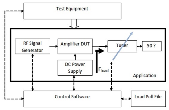
Fig 1: The test arrangement for load pull appears conventional, with an amplifier driving the DUT which in turn drives a 50-ohm load, but there’s an unusual tunable-impedance element between the DUT and load. (Source: Keysight Technologies)
Q: How is this tuner physically constructed?
A: Most commonly, and still used, it was done using a mechanical slide-screw tuner with two parallel plates and a center conductor, and a metallic probe (or slug), Figure 2. As the probe’s position changes, the phase of the reflected waveform changes. In this way, it can present nearly any impedance to the DUT. In the earlier systems, the movement of the probe was controlled by a calibrated knob for the lead-screw. Modern load-pull setups often use a motorized version where the motor and thus position is controlled by test software, which is certainly easier than manual adjustment, Figure 3, but the electrical principle is the same.

Fig 2: The tunable element is a mechanical arrangement with a sliding element; as it changes position, it affects the incident and reflected wave ratio and so takes on different impedance values. (Source: Maury Microwave Corporation)
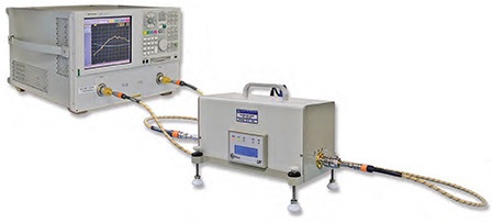
Fig 3: The sliding element can be automated with a computer-controlled motor to move the slider, and so simplify and speed the test procedure. (Source: Maury Microwave Corporation)
Q: What kind of signal(s) does the RF signal generator need to provide?
A: It depends on the intended application of the DUT. It can be a standard two-tone signal, with a spectrum analyzer (or multiplexer with several power sensors) used to read the RF power at each of the two frequencies as well as the power levels at intermodulation frequencies. For more complicated applications such as high-end radar, it can be continuous wave (CW), pulsed-CW, single-tone, or other modulated signals, to cite some possibilities.
Q: Is the load-pull test process all done?
A: Not at all. The traditional version of load pull, known has scalar load pull, is being superseded by a more comprehensive version called vector load pull, which yields much more information and insight.
Q: What’s the simpler, scalar load pull?
A: In this test, a power meter is used as the primary measurement instrument, and power is a scalar (non-vector) parameter, Figure 4. The power is measured at a reference plane, and then this value is “corrected” to compensate for the unavoidable passive losses between the power sensor and the DUT, including the loss within the tuner (which changes as a function of impedance/probe position). The standard wideband power sensor measures all power including the fundamental and harmonic frequencies.
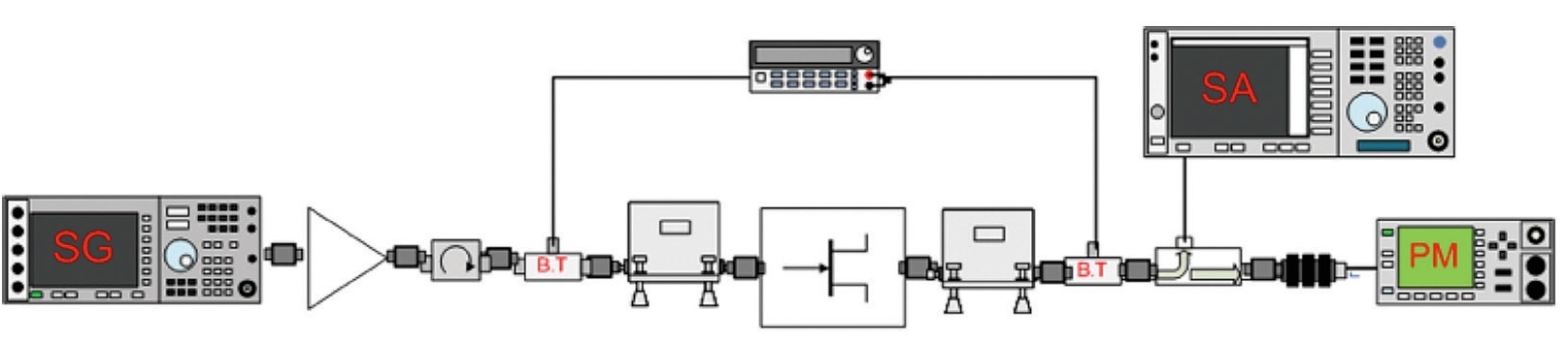
Fig 4: The basic scalar load-pull test using a signal generator (SG) and spectrum analyzer (SA) as it read the power via the power meter (PM). (Source: Maury Microwave Corporation)
Q: Then what is vector load pull?
A: A vector has both magnitude and phase. Vector load pull uses the same general arrangement as scalar load pull. However, it replaces the basic scalar power meter with a vector network analyzer (VNA) is used to measure the DUT signal, Figure 5, and provide the data (a1, a2, b1, b2) needed to generate the full set of four S-parameters of the two-port DUT. (If you are not familiar with these scattering parameters, better known as S-parameters, they are essential to understand and use for most RF design and analysis.) Note that VNAs were once relatively scarce and costly pieces of RF test equipment, but they are now almost as common and necessary as the spectrum analyzer and oscilloscope, as prices have come down and the need for them has increased.
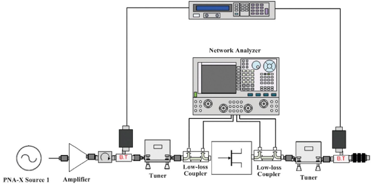
Fig 5: The vector approach adds a network analyzer to provide more comprehensive results. (Source: Maury Microwave Corporation)
The references will provide more insight, from different perspectives, into load pull, its execution, and its implications.
References
- Impedance matching and the Smith chart, Part 1
- Impedance matching and the Smith Chart, Part 2
- Microwave/Millimeter Wave interconnects, Part 1: Coaxial cables
- Microwave/Millimeter Wave interconnects, Part 2: Connectors and cable assemblies
- A Beginner’s Guide To All Things Load Pull
- Power amplifier design and load pull measurements in practice
- Power Amplifier Design 2
- Microwaves 101: Load Pull for Power Devices
- Overcoming the Challenges of mmWave, On-Wafer Load-Pull Measurements for 5G


Leave a Reply
You must be logged in to post a comment.