Part 4 concludes this FAQ with some fabrication issues and at substrates with performance which is multi-GHz-compatible and goes beyond that available using FR-4 material.
Q: What’s the set-up situation for PC board fabrication?
A: The production-level fabrication process is optimized for runs of tens, hundreds, and thousands of boards, as there is a set-up and tooling time and cost. However, there are specialty vendors who only do quick-turn, short set-up fabrication which is very useful for prototypes, pilot runs, and test fixtures. However, there can be problems when transitioning from a low-volume PC board fabrication arrangement to a higher-volume fabrication facility, so a pilot run is often required at the regular production facility.
Q: Are there alternatives, especially if I only will need a few boards such as for a test fixture?
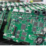
A: Yes, there are. Companies such as LPKF offer “do it yourself” low-volume fabrication systems, which can be used in-house or at a special facility (Figure 1). One type uses ultra-thin bits to mill away the copper layer via a controlled depth router and thus reveal the desired PC board tracks. Another type uses a laser to burn away the undesired copper. Both of these units remove the copper, drill holes, and even electroplate the vias, and can be used for multilayer designs. Production time for a single board is typically two to six hours, which is much slower than higher-volume mass production rates but is suitable for “we need it, and we need it now” or low-volume situations.
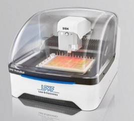
Fig 1: Machines such as these from LPKF can make high performance, tight tolerance PC board “in house” using either micro-milling and routing or laser ablation; though not a good fit for volume production, they are a well suited to prototypes and low-volume test fixtures. (Image source: LPKF Laser & Electronics AG)
Q: So far, we have focused on FR-4, but what is being done to meet the next stages of PC board requirements?
A: Many of the fabrication issues related to FR-4 will apply to other glass-epoxy or similar substrates, and the extensive knowledge base and experience remains relevant.But…and it’s a big “but”, the FR-4 material itself is not suitable for advanced designs in the multi-GHz range, such as automotive radar, 5G designs, and more — and that’s where the RF industry is heading.
Q: Why is FR-4 not suitable?
A: It is due to both electrical and mechanical reasons, and these are closely linked. First, the mechanical stability of FR-4 and the temperature coefficient of those parameters, while quite good, are not good enough for multi-GHz designs — that’s a region of the spectrum where even the tiniest shift in dimensions or other characteristics also change the electrical specifications as well. Further, the FR-4 substrate itself does not offer the stringent electrical-performance specifications demanded by those frequencies, and the moisture absorption of FR-4 is too high.
Q: What are some of the parameters of interest at these frequencies?
A: Among them are dielectric constant (er), loss factor (tδ), dielectric breakdown voltage, leakage current, tensile strength, the shear strength, moisture absorption, the glass transition temperature (Tg), and the Z-axis thickness, along with their temperature coefficients. Each of these must not only meet or exceed an acceptable value but must be very stable and consistent despite temperature and humidity changes.
Q: So, what is being done?
A: Vendors of PC board material have developed new, advanced substrates which are more compatible with the needs of these frequencies. These substrates are highly engineered materials in every respect, including the material itself, production consistency, and even parameter measurement. Their characteristics are a significant part of any model of the circuit, and the PC board is much, much more than just a passive physical platform or carrier for components and interconnects.
Q: Who is doing this work?
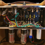
A: One of the leading vendors in the development, characterization, modeling, and production of these new PC board substrates is Rogers Corp. They offer various laminates, each having combinations and tradeoffs of electrical and mechanical characteristics optimized for specific applications (Figure 2). They also provide application notes and articles which discuss the subtleties of these boards and measurement, including the performance of PCB through-hole plating on 5G-related performance, see Reference 9.
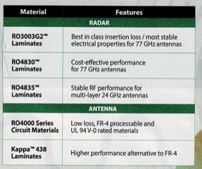
Fig 2: FR-4 may not always meet the diverse needs of multi-GHz RF circuits, so vendors have engineered substrate materials targeting specific application priorities. (Image: Rogers Corp.)
Q: Can I measure the PC board substrate properties?
A: Probably not….these PC boards now come with their own set of S-parameters for example, and measuring the various key specifications is difficult. Even experienced specialists have difficulty doing so and have perspectives (and disputes) with respect to various test and evaluation arrangements.
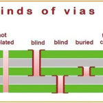
For example, determining the complex dielectric permittivity of widely used substrate and laminate sheets ranging in thickness from 0.3 to 3-mm thick, over just the 3- to the 6-GHz range, requires electromagnetic modeling in addition to actual measurements, References 10 and 11. Even measuring and modeling the performance of the vias is complicated, but must be done as these vias carry and affect the multi-GHz signals.
In summary, the humble and often underappreciated PC board is much more than a physical carrier and electrical interconnect. As the foundation on which the circuit design is implemented, its material, design, fabrication, modeling, and performance is an integral part of the product. Advanced and sophisticated materials, production, and test are just a few of the issues which must be applied to the PC board for a successful project and product.
References
- Wikipedia, “FR-4”
- PCB trace calculators: MustCalculate, Bittele Electronics Inc. and Trance-Cat
- Wikipedia, “Printed circuit board”
- Wikipedia, “Via (electronics)”
- SEEED Studio, “Printed Circuit Board(PCB) Material Types and Comparison”
- Al Wright, Epec LLC., “PCB Vias – Everything You Need To Know”
- Microwaves101, “FR-4”
- All About Circuits, “Which Via Should I Choose? A Guide to Vias in PCB Design”
- Rogers Corp., “Evaluating PCB Plated Through Holes For 5G Applications”
- John W. Schultz, Compass Technology Group, “A New Dielectric Analyzer for Rapid Measurement of Microwave Substrates up to 6 GHz”
- Rogers Corp., “Characterizing Circuit Materials at mmWave Frequencies”
- Rogers Corp., “Laminate Materials Simultaneously Increase μ and ε, Reducing Antenna Size”
Related EE World Content
- What are RF waveguides? Part 1: context and principles
- What are RF waveguides? Part 2: implementation and components
- Passive microwave components, Part 2: couplers and splitters
- Passive microwave components, Part 1: isolators and circulators
- Next-gen laminates improve insertion loss in automotive radar sensor applications
- High-impedance laminates help reduce antenna size
- Laminates for 5G and other millimeter wave applications

Leave a Reply
You must be logged in to post a comment.