• Skip to primary navigation
  • Skip to main content
  • Skip to primary sidebar
  • Skip to footer

Electrical Engineering News and Products

Electronics Engineering Resources, Articles, Forums, Tear Down Videos and Technical Electronics How-To's

  • Products / Components
    • Analog ICs
    • Connectors
    • Microcontrollers
    • Power Electronics
    • Sensors
    • Test and Measurement
    • Wire / Cable
  • Applications
    • Automotive/Transportation
    • Industrial
    • IoT
    • Medical
    • Telecommunications
    • Wearables
    • Wireless
  • Resources
    • DesignFast
    • Digital Issues
    • Engineering Week
    • Oscilloscope Product Finder
    • Podcasts
    • Webinars / Digital Events
    • White Papers
    • Women in Engineering
  • Videos
    • Teschler’s Teardown Videos
    • EE Videos and Interviews
  • Learning Center
    • EE Classrooms
    • Design Guides
      • WiFi & the IOT Design Guide
      • Microcontrollers Design Guide
      • State of the Art Inductors Design Guide
    • FAQs
    • Ebooks / Tech Tips
  • EE Forums
    • EDABoard.com
    • Electro-Tech-Online.com
  • 5G

Reducing ringing or reflections by controlling impedance lines

May 1, 2018 By Janet Heath 1 Comment

What is a controlled impedance line? For one thing, the term has to do with Printed Circuit Board (PCB) traces and layouts, which get more complex with higher frequency signals. Generally, you need not worry much about controlling impedance in traces unless you are working with signals at or above 50 MHz. However, most of the interfaces we use today operate at higher than 50 MHz (e.g., USB). When you are designing a PCB, the layout and the length of transmission lines of high speed signals matter.

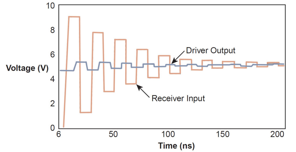
In an ideal world, the signal energy coming out of a pin would travel through PCB traces and be wholly absorbed by the load. However, if energy is not completely soaked up by the load (receiver), residual energy can get reflected back through the PCB trace, reaching the original source of the energy at the output pin (driver). Reflected energy acts like a wave and adds or subtracts to the original signal, causing “ringing.” Resonance can develop at a signal’s characteristic frequency. The result is an unpredictable and confusing signal.

controlling impedance lines

Figure 1: Example of a reflected signal due to mismatched transmission impedance. The signal will keep reflecting back and forth between receiver and driver until the signal is absorbed by the load or the losses in the transmission line (PCB traces). (Image: AN022, Pericom)


One way to fix this is to have electrically short traces. If the reflected signal is large, it will affect signal integrity with erratic behavior. (Ringing is more prevalent with step signals.) If an output signal is reflected over an electrically short trace, the reflections are likely to be overpowered by the rising or falling edge of the original signal. A rule-of-thumb: an electrically short trace is one that is not longer than one-third the rise time of the signal’s edge. That is, there is vulnerability to ringing if a trace is longer than one-third of the rise time of the step signal. According to Analog Devices’ Dealing with High-speed Logic (PDF), “A more conservative rule is to use a 2-inch (PCB track length)/[per]nanosecond (rise/fall time).” In other words, the signal edge of a high-speed step signal with a rise or fall time of 4 ns will be less prone to problematic ringing if the PCB trace is equal to or less than 8 inches. Others use an even more stringent rule-of-thumb to keep trace length less than one-sixth of the electrical length of the rise time of the signal’s edge.

Otherwise, the PCB trace (or track) should be terminated in its characteristic impedance. The unmatched impedance of transmission lines (e.g., PCB traces) can cause reflections as the impedance along the length of the transmission line changes. The source’s impedance needs to match the impedance of the trace and the load. Matching the impedance can be accomplished by tying the trace down with a resistor near the source or the load.  Keeping traces short is another way to combat reflections and ringing.

FR4 is a standard material used in PCBs. A signal’s speed in FR-4 travels about six inches per ns (6”/ns). With the most stringent rule to keep trace length less than one-sixth (1/6) of the electrical length of the rise time of the signal’s edge, then signal with a 1 ns rise time would need termination for traces longer than 1 inch.

There are various ways to impedance match. High-speed signals tend to use resistors in series to terminate traces, but high-speed bus lines tend to get terminated with resistance in parallel.

controlling impedance lines

Figure 2: Example of parallel termination (end termination) where Z0 is the impedance of the trace. The value of resistor R should be Z0, located close to the receiver, and connects to either ground or the supply voltage. (Image: AN022, Pericom)

Rough estimating rules can be used in planning stages, but you should do a simulation or the heavy math the old-fashioned way using closed-form transmission line equations. To learn more about reducing ringing and controlled line impedance, consider an application note (AN022) from Pericom (Diodes, Inc.) titled Solutions to High-Speed Board Design (PDF). Other resources include Tektronix’ Fundamentals of Signal Integrity (PDF) and Texas Instruments’ High Speed Layout Guidelines (Rev A) (PDF). PCB layout gets more complicated with higher frequency signals.

You may also like:


  • Impedance matching and the Smith Chart, Part 2

  • What is common-impedance coupling?
DesignFast Banner version: 22e7f758

Filed Under: FAQ, Featured Tagged With: basics, diodesinc, FAQ, pericomsemiconductor, tektronix, texasinstrumentsinc

Reader Interactions

Leave a Reply Cancel reply

You must be logged in to post a comment.

This site uses Akismet to reduce spam. Learn how your comment data is processed.

Primary Sidebar

EE Training Center Classrooms

EE Classrooms

Featured Resources

  • EE World Online Learning Center
  • CUI Devices – CUI Insights Blog
  • EE Classroom: Power Delivery
  • EE Classroom: Building Automation
  • EE Classroom: Aerospace & Defense
  • EE Classroom: Grid Infrastructure
Search Millions of Parts from Thousands of Suppliers.

Search Now!
design fast globle

R&D World Podcasts

R&D 100 Episode 7
See More >

Current Digital Issue

April 2022 Special Edition: Internet of Things Handbook

How to turn off a smart meter the hard way Potential cyber attacks have a lot of people worried thanks to the recent conflict in Ukraine. So it might be appropriate to review what happened when cybersecurity fi rm FireEye’s Mandiant team demonstrated how to infiltrate the network of a North American utility. During this…

Digital Edition Back Issues

Sponsored Content

Positioning in 5G NR – A look at the technology and related test aspects

Radar, NFC, UV Sensors, and Weather Kits are Some of the New RAKwireless Products for IoT

5G Connectors: Enabling the global 5G vision

Control EMI with I-PEX ZenShield™ Connectors

Speed-up time-to-tapeout with the Aprisa digital place-and-route system and Solido Characterization Suite

Siemens Analogue IC Design Simulation Flow

More Sponsored Content >>

RSS Current EDABoard.com discussions

  • Help with Verilog replicate operator
  • ESP Serial Communication Problem with RS232
  • How to mark layer comments in CAP of spef file using StarRC
  • MAX5389 resetting by noise
  • Simulation of resonator in HFSS

RSS Current Electro-Tech-Online.com Discussions

  • Will Header and socket hold this PCB OK?
  • Relaxation oscillator with neon or...
  • software PWM
  • MPlab8 remove page breaks in list file
  • ATOM Diy module

Oscilloscopes Product Finder

Footer

EE World Online

EE WORLD ONLINE NETWORK

  • 5G Technology World
  • Analog IC Tips
  • Battery Power Tips
  • Connector Tips
  • DesignFast
  • EDABoard Forums
  • Electro-Tech-Online Forums
  • Engineer's Garage
  • Microcontroller Tips
  • Power Electronic Tips
  • Sensor Tips
  • Test and Measurement Tips
  • Wire & Cable Tips

EE WORLD ONLINE

  • Subscribe to our newsletter
  • Lee's teardown videos
  • Advertise with us
  • Contact us
  • About Us
Follow us on TwitterAdd us on FacebookConnect with us on LinkedIn Follow us on YouTube Add us on Instagram

Copyright © 2022 · WTWH Media LLC and its licensors. All rights reserved.
The material on this site may not be reproduced, distributed, transmitted, cached or otherwise used, except with the prior written permission of WTWH Media.

Privacy Policy