by Matthew Ballance, Mentor, a Siemens Business
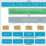
The raison d’etre for portable stimulus is reuse. The Accellera Portable Stimulus Standard (PSS) promotes test intent reuse throughout the verification process and across the multiple engines on which those verification runs are performed. Test intent captured as portable stimulus models enable test reuse from the IP to SoC levels and boost test-creation productivity.
As users consider applying portable stimulus, one immediate realization is the limited amount of portable stimulus content currently available within their organizations. Fortunately, there are many existing descriptions and formats within an organization that can be reused to create portable stimulus descriptions.
UVM register models and SystemVerilog classes and constraints are examples of existing descriptions that can be productively reused with a portable stimulus.
In this four-part series, we will show you how to use UVM and SystemVerilog descriptions that you may already have, so you can jump-start the creation of portable stimulus models. We will begin with UVM register models.
UVM register models are heavily used at the block and subsystem levels to simplify interacting with device registers. The information captured within a register model description – register addresses, which fields can be written, etc. – is very helpful in creating SoC integration tests. In addition, this information is captured in a machine-readable way which makes it easy to automate reuse of this key portable stimulus information.
The UVM library provides built-in, directed sequence tests that iterate through a UVM register model to check the reset value of registers and confirm that registers are accessible. These sequence tests are incredibly useful at the IP level, but reusing them at the subsystem and system levels remains difficult.
This is where the PSS comes in. Capturing register-test intent in a portable stimulus model makes register-test functionality portable from the IP to the SoC level and provides more flexibility in controlling which registers are checked in a given test run.
Splitting the Atom: Test Intent and Realization
Separating test intent and test realization, which are typically merged in a directed test, is a core element of portable stimulus, and this division is key to enabling test intent to be easily retargeted across environments. Test intent is the high-level design of what to test. Test realization is the mechanism by which that test is carried out.
In the case of testing a register model, test intent looks something like this: select a register from the register block; select a read/write field from the register and select a bit within that field to test.
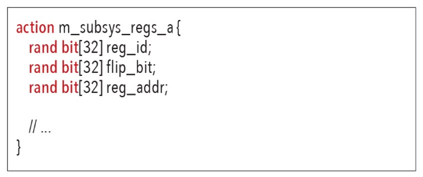
The test intent described above is independent of whether we are verifying a block, subsystem, or SoC level design. It is also independent of whether a SystemVerilog environment or an embedded-software environment is targeted. The test intent for testing a single register is captured by the PSS code below, where: reg_id captures the register being tested, flip_bit captures the bit within the register to be tested, and reg_addr captures the address of the field in the memory maps.
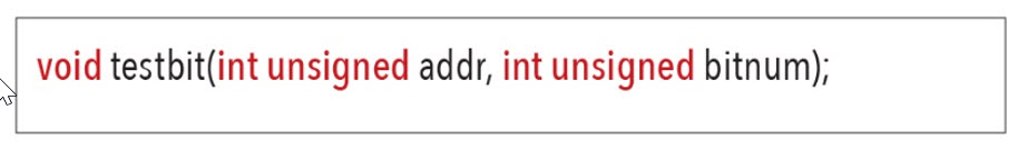
Designing the test realization with portable stimulus in mind allows us to design a common API that will be available in all environments. For example, we might specify that a method named testbit will be available in all environments and that this method will test the ability to modify the specified bit. The function prototype for such a function is shown below.
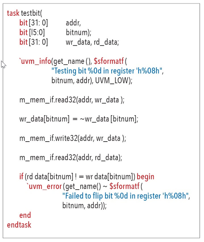
In a SystemVerilog IP or subsystem level environment, we could implement this method as a task within a UVM sequence. The SystemVerilog task shown below uses a memory-access API to read and write memory and implements the register bit-test operation by reading the current value of the register, negating the target bit of the register and writing the new register value, and reading back the register address and checking whether the bit retains its value.
Birth of a Subsystem Register ModelIn this case, the test will continue to run if an error is encountered. This is pretty typical of UVM tests. However, an embedded software environment has different constraints. The example below shows an implementation of the testbitfunction for an embedded processor. This approach is very similar to the SystemVerilog version, though the specifics are different. One of the biggest differences is that, in this case, we assume if a register bit test fails, we will end the entire test.

Now we will create a subsystem UVM register model. The example subsystem in figure 1 has a processor, two Ethernet controllers, and two DMA engines.
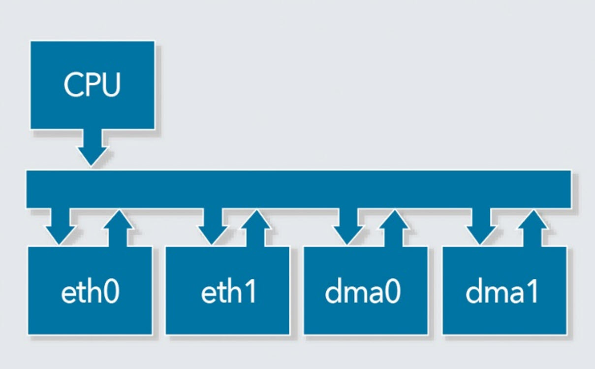
Figure 1 – Simple Subsystem
A UVM register model was created at the block level, most likely using a register-creation tool (see figure 2), for the Ethernet and DMA controllers during verification.
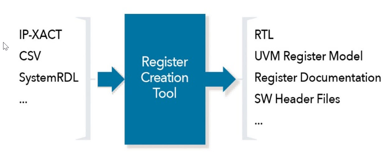
Figure 2 – Register Creation Tool
At the subsystem level, a register-creation tool may help us to assemble a register model for the entire subsystem. Or we may simply take the individual block-level register models and assemble the subsystem-level register model manually. The code below assembles a subsystem-level register model from the Ethernet and DMA controller register models. Not much code is required: only the available registers in the design, and their addresses, and the fields within those registers and any access restrictions.
What might be surprising is just how quickly the number of registers accumulates. By the time we’ve created a register model for just two Ethernet controllers and two DMA controllers, we have 989 registers with testable fields. Imagine how many registers a full SoC contains!
Now that we’ve seen how to capture a subsystem or SoC level register model, how do we proceed to create register-access tests? First, we need to create a PSS model of the register-access test intent. Then, we need to connect that test intent to specific verification environments with test realization.
The next article in this series will show you just how to do that.
 Matthew Ballance is a Product Engineer and Portable Stimulus Technologist at Mentor Graphics, working with the Questa inFact Portable Stimulus product. Over the past 20 years in the EDA industry, he has worked in product development, marketing, and management roles in the areas of HW/SW co-verification, transaction-level modeling, and IP encapsulation and reuse. Matthew is a graduate of Oregon State University.


Leave a Reply
You must be logged in to post a comment.