Atomic clocks have shrunk from room-sized assemblies down to PC-board mountable modules, admittedly with lower performance than their big siblings but still far better than crystal-based timing alternatives.
Every engineer knows that developing a viable design and product is not just a matter of theorizing a design, identifying the constituent components, or building a single prototype. (There’s a saying that scientists can build one unit – but just the one – while engineers and production personnel have to figure out how to build the rest.)
To be usable in the field, the CSAC must be highly tolerant of changes in ambient and operating temperature and vibration and shock. Managing thermal paths is critical to stable performance. In addition, developers of the CSAC approach needed to develop a construction technique compatible with low-cost, higher-volume batch manufacturing.
Consider the suspension of the resonance cell. The suspension system must minimize conductive thermal losses from the heated resonance cell while providing the necessary mechanical support for a rugged device. The degree of thermal insulation required to meet the power budget significantly limited the choice of materials and the beam dimensions of the suspension system. The suspension system must also be stiff and rugged.
This combination of constraints led to the development of a novel suspension system using strained polyimide support tethers. Polyimide has extremely low thermal conductivity (less than 0.2 W/m-°C) and a high strain yield (typical 3%). To make the device robust against large accelerations, the suspension beams are angled to resist motion in tension, rather than bending, mode.
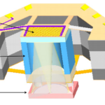
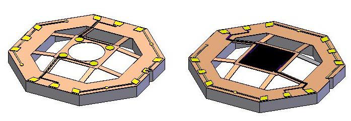
Among the many goals for the cell suspension was a volume of less than one cubic centimeter, resonant frequency above 2 kHz, and shock load above 1500 g. Two sets of suspension systems were used to realize this, one on top and one on the bottom of the resonance cell (Figure 1). The lower suspension has leads and bond pads for flip-chip attachment of the VCSEL/Detector assembly, while the upper suspension includes the cell heater and temperature sensor.
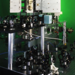
The complete resonance cell is packaged, in turn, in a unique and carefully designed, and modeled assembly (Figure 2).

Of course, such a technology doesn’t come cheap. The CA65 is priced at about $5,500 in single-unit orders and half that amount in lots of 250 or more. Nonetheless, this price may be a bargain for what a CSAC can do. While the SA45 (predecessor to the SA65) is not a mass-market product on the scale of a smartphone processor, Microchip says they have sold well over 100,000 units of that CSAC. This is a testament to users’ demand and the ability to go from a laboratory prototype or pilot run to a standard-production device.
A long path to success
Success in such projects doesn’t happen quickly or easily, as there is so much R&D to be done, followed by prototypes, performance assessments, design evaluation, and much more. When you are looking at the extreme levels of performance desired, every aspect of the design, materials, and fabrication is critical. For example, every constituent material’s thermal and mechanical characteristics, including their short- and long-term aging and drift, are just some of the issues that must be investigated, and some are still not fully understood. Adding to the challenge was making this a standard production item without hand-crafting and hand-tuning each unit.
The CSAC concept began as a Defense Advanced Research Projects Agency (DARPA) project around 2000, involving scientists, atomic and optical physicists, “time” experts, materials specialists, and electronic specialists at Charles Stark Draper Laboratory, Symmetricom Inc, and Sandia National Laboratories.
In 2011, Symmetricom introduced the SA45 chip-scale atomic clock (CSAC) based on cesium-clock technology (Microsemi acquired Symmetricom in Oct 2013; in turn, Microsemi was acquired by Microchip Technology in 2018). The SA45 featured accuracy, which was two orders of magnitude better than that of oven-controlled crystal oscillators (OCXOs), and up to four orders of magnitude better than temperature-controlled crystal oscillators (TCXOs).
That level of performance, while not as good as rack-mounted clocks or NIST clocks, still provided a significant improvement and opened up new applications where this level of additional accuracy, along with favorable CSWaP metrics, made a meaningful difference. The physics, R&D, materials, test, and production of these devices is obviously a multilayered, complicated story. The published academic and overview papers in the References can fill in many more details. Just as important, they can also provide the names of the key contributors via the bylines.
EE World Related Content
GPS is a ubiquitous and problematic technology
Basics of GPS receivers
GPS, Part 1: Basic principles
GPS, Part 2: Implementation
Atomic clock works from 5 V, outputs CMOS-compatible signals
Chip-scale atomic clock produces super-stable frequencies
Miniaturized rubidium atomic clock maintains high degree of synchronization to reference clock
Commercial space Chip Scale Atomic Clock module is radiation tolerant
Chip-scale atomic clocks fit in compact quarters
Quartz crystals and oscillators, Part 1: Crystal basics
Quartz crystals and oscillators, Part 2: Advanced crystals
References
- Comprehensive Guide on Polyimide (PI)
- National Institute for Standards and Technology, “NIST-F1 Cesium Fountain Atomic Clock”
- National Institute for Standards and Technology, “Definitions of SI Base Units”
- National Institute for Standards and Technology, “Analysis of Time Domain Data” (Allan Deviation).
- Stanford Research Systems, “Rubidium Oscillator PRS10”
- Stanford Research Systems, “Frequency Standards: PRS10 — Rubidium frequency standard with low phase noise”
- Symmetricom, “The SA.45S Chip-Scale Atomic Clock”
- Wikipedia, “Allan variance.”
- Microchip Technology, CSAC SA65 Data Sheet
- Microchip Technology, “Chip-Scale Atomic Clock (CSAC) SA65 User’s Guide”
- Microchip Technology, Robert Lutwak, “Tactical Atomic Clocks”
- Lutwak, et al; 36th Annual Precise Time and Time Interval (PTTI) Meeting, “The Chip-Scale Atomic Clock – Low-Power Physics Package” (2004)
- Mescher, et al, “An Ultra-Low-Power Physics Package For a Chip-Scale Atomic Clock”
- 2011 Stanford PNT Symposium, Robert Lutwak, “The SA.45S Chip-Scale Atomic Clock”
- US Patent 6,927,636 B2 (2005), “Light stabilization for an optically excitable atomic medium”
- US Patent 6,320,472 B1 (2001), “Atomic Frequency Standard”
- US Patent 7,215,213 B2 (2007), “Apparatus and system for suspending a chip-scale device and related methods”