
The electronically controlled, cam-free internal combustion engine seemed like a good idea, but technical and market realities stifled its acceptance.
Part 1 provided the context for the classic cam-based ICE valve system and alluded to some limitations. This part looks at approaches that have been devised to overcome these issues to some extent.
This pushrod-and-cam system works well, but it has some weaknesses, especially in high-performance (high power and torque) engines. The mass of pushrods limits the system’s responsiveness. There are issues of initial-tolerance buildup in the valve train, and inevitable wear of components results in numerous points for wear and slack.
One way to overcome these drawbacks is using an overhead-camshaft design, which is common in most high-power engines. A belt or chain from the crankshaft still drives the camshaft, but the camshaft is located on top of the engine above the cylinder heads. In this configuration, the camshaft can directly control the rocker arms, eliminating the pushrods’ weight and tolerance problems. In a dual-overhead-camshaft design, one camshaft controls the inlet valves, and another camshaft controls the exhaust valves. This design allows for precise control over each of these valves, which are keyed to the engine rotation.
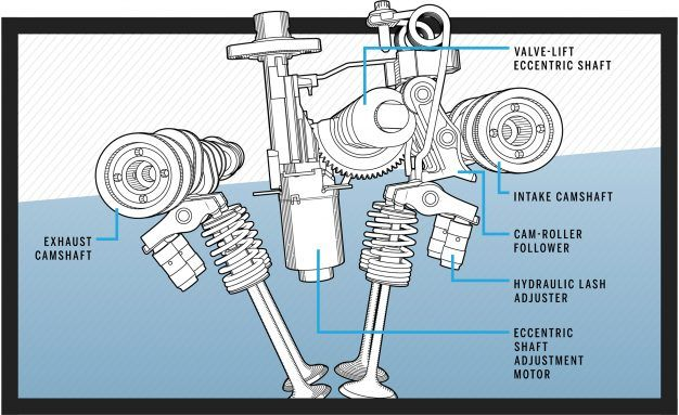
Automotive engineers can design a cam-based system with some timing variability, if desired, by shifting the timing cycle slightly depending on engine rpm and other factors. However, such a design is more complex and costly and still remains relatively inflexible. Some engines vary the camshaft timing in accordance with rpm by using a mechanism to shift the camshaft timing with respect to the crankshaft. This can be done by controlled “twisting” of the camshaft or via a small electric motor (Figure 1).
Although either of these approaches can improve performance, they add complexity and allow only limited or fixed timing shifts. Further, all the engine valves undergo the same shift, and thus all cylinders operate with the same revised settings. There is no easy option for shutting off one or a few cylinders to save on fuel if they are not needed, such as when cruising or going downhill. (Note that there have been some engines in high-end luxury vehicles that did try to have individual cylinder cut-off, but they have generally been commercial failures for a variety of reasons.) In short, the fixed-shift approach lacks the flexibility, wide variability, and dynamic adjustability that a camless system could provide, at least in theory.
The cam-based system has other limitations. Fixing problems is not a simple operation because the technician must remove, reassemble, and remeasure all of the system’s parts and make some small, often interactive adjustments in an iterative procedure. In addition, the system is still inherently inflexible because the mechanical shape and dimensions of the cam’s lobes and the associated linkages and pieces set the basic timing unless the previously mentioned special add-on techniques or other approaches are used.
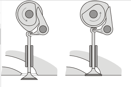
It’s not that designers haven’t tried to do better – they have, and have succeeded, but also have hit the wall, so to speak. The cam design has been advanced to very high levels of performance. The advances include the use of “desmodromic valves”, which have an interesting feature: they are positively closed by a cam and leverage system rather than by a more conventional spring. They have different controls for their actuation in different directions (Figure 2). This arrangement was used in some high-end vehicles for a short period, but the complexity outweighed the benefits.
Designing the desired cam shape is a multifaceted mechanical challenge. It includes tradeoffs among factors such as open/close distance, open/close rate, acceleration and deceleration, actual timing, and many other items. Modern engine modeling takes into account not only the basic cam shape itself – which is a relatively static analysis – but also significant factors such as inertia and other dynamic factors associated with moving masses (such as the valves, rockers, and pushrods) and rotating masses (the crankshaft and cams) at high speed.
Despite this inflexibility, the present-day performance of a cam-based system is a testament to the system’s refinement, consistency, and repeatability over many years and miles. It’s been proven more than just about any other mass-market mechanism. Still, as auto vendors looked to squeeze even more performance out of the internal combustion engine, they looked to radically different valve-control technologies. The next part of this article looks at a possible alternative: the electronically controlled, camless engine-valve system.
Related EE World Content
Understanding stop/start automobile-engine design, Part 6: Responses and work-arounds (has links to previous Parts 1 through 5)
Digital Valves Open Up New Possibilities For Engines
Single element, tooth-detecting speed sensor IC
References
- Car and Driver, “Variable Valve Timing Explained: An Appreciation of How Quickly Engines Operate”
- New Atlas, “World’s first fully digital valves open up engine possibilities”
- Motor Authority, “Fully digital valves could change the future of the combustion engine”
- Motor Authority, “ ‘Engineering Explained’ tackles Koenigseggs camless engine”
- Clemson University, “Electronic Valve Timing Control”
- Clemson University, “Camless Engines”
- Motor1, “Fully Digital Valves Could Massively Improve The ICE”
- Wikipedia, “Camless Piston Engine”
- Top Gear, “Here’s how the Koenigsegg Gemera’s 600bhp camless engine works”
- Hackaday, “Where Are All The Camless Engines?”
- The Wall Street Journal, “Gas Engines, and the People Behind Them, Are Cast Aside for Electric Vehicles”
- Wikipedia, “Desmodromic valve”
- Virtual Energy, “Camless Hydraulic Valve Actuation (HVA)”
- Machine Design, “Improving Car Engines with Advanced Variable Hydraulic Valves”
- Skill-Lync, “Design and MBD Simulation of IC Engine Valve Train and FEA Analysis of Rocker Arm”
- University of Waterloo, “New Fully Flexible Variable Valve Actuation System”
- University of Waterloo, “New Fully Flexible Variable Valve Actuation System”
- University of Waterloo, “Hydraulic Variable Valve Actuation System: Development & Validation”