Modulation is considered to be a radio frequency (RF) technique which refers to modifying a periodic waveform with another waveform. For example, frequency modulation takes an RF “carrier” signal (sine wave) at say 88MHz and varies the frequency slightly, based on your “modulating” signal which will most likely be an audio signal up to 15kHz or so. Similarly, amplitude modulation may take a 1.6MHz carrier signal and vary the amplitude using an audio signal. The reason for using RF modulation is to be able to generate signals which can later be separated from other RF signals in the spectrum just to look at (or listen to) the one you want. So, you can listen to the radio station on 88MHz without interference from the thousands of other signals in the whole RF spectrum.
However, there are other uses for modulation which provide some of the same benefits when used with RF signals. One use is for optical signals, such as those used for television remote controls. It is unlikely that many TV remotes operate simultaneously, but there could be multiple devices using infrared light to control them. There will also be varying levels of ambient light to deal with. Separating which signal is meant for which device is simply a matter of encoding the data in a unique way or adding an identifying code to the data. The benefit of modulation is being able to reject other optical signals, in particular ambient light. A simple modulation scheme would be to encode your data so when the infrared LED is on, the data is a logic 1 and when it is off, the data is a logic zero. A more robust modulation scheme uses a carrier frequency, often 38kHz, and so a 38kHz burst of LED light represents a logic 1 rather than merely the presence of light. In this way it is a lot more like an amplitude modulated RF signal with 100% modulation.
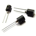
Chips exist to help to make a remote control link in this way, such as the Vishay TSOP4838 and similar devices. The series includes devices working from a 30kHz to 56kHz carrier frequency.

The key feature here is the bandpass filter at 38kHz, or whatever frequency device you have selected. This scenario creates a compact receiver which would otherwise take a fair bit of discrete circuitry. It is the demodulator rather than the modulator. Modulation is pretty straightforward. Most microcontrollers have the ability to generate a fixed frequency, low-frequency clock output or PWM (pulse width modulation), so you only turn a suitable signal on and off to encode your data and modulate the LED.
RF modulation often uses different techniques, partly because you want to minimize spurious signals and components. Perfect RF modulation or mixing comes from the pure multiplication of two sine waves.
sin(x).sin(y) = [cos(x-y) – cos(x+y)]/2
So, if x = w1t and y = w2t, the result of a pure multiplication is sum and difference of the two frequencies. This formula is a fundamental building block of RF theory and also has uses in other signal processing scenarios.
The Gilbert cell is the purest form of a double-balanced mixer which can produce a good multiplication if signal levels are small. With larger signals there will be additional harmonic and spurious components. I have shown the MC1496 double balanced mixer before when discussing biasing:

The outputs connect to a positive supply with resistors. Ideally, you would take the differential output rather than just using one of them. If you apply 100kHz and 90kHz to the inputs, this is the result (viewing a single output):
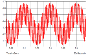
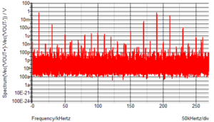
The 10kHz difference frequency is evident. The 190kHz is not so obvious but is easily seen on a Fourier transform plot, as are the unwanted products due to the mixer not being a perfect multiplier. In particular, you can see a strong 210kHz as well as 170kHz.
A simpler mixer is simply a switch. For RF circuits this can be a ring modulator with two transformers and four Schottky diodes such as the TUF-1+ from Mini-Circuits.

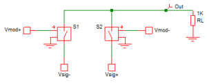
For lower frequencies, it can simply be an analog switch. The theory with either type of modulator is that you are still doing multiplication but instead of multiplying two sine waves, one of the waveforms is a square wave, and you are multiplying one sine wave by +1 and -1. The effect can be illustrated using a simple circuit with ideal switches. In the example below the two switches are driven with the opposite polarity (Vmod+ and Vmod-) and the source signal also has two polarities (Vsig+ and Vsig-). So, the switches alternately select the inverted and non-inverted signals.
The waveforms below show that more clearly.

You can see that the two modulating signals are the resultant waveform on the output. You should also be able to see a low-frequency component. A Fourier transform of the output shows the other components of the output:
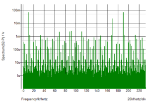
You get more unwanted signals at higher levels than the Gilbert cell mixer, but the basics are still there – the 10kHz difference signal and the 190kHz sum. A strong 170kHz frequency is present, as well as many other frequencies.
So, why would you be interested in modulators/mixers except for RF work? Well, there are lower frequency uses in signal processing such as phase shift optical distance measurement. A modulated light source can be used to measure distance using the time of flight method. The received signal will be phase shifted due to the time it takes light to travel to the target and back. The phase shift will be subtle because the speed of light is very high. However, if you mix the returned signal with a signal close to the modulating signal and filter the result to extract the low-frequency component, the phase shift is preserved. So, instead of trying to measure the phase shift of a 20MHz or 200MHz signal you can be measuring the phase of a 10kHz signal, or whatever frequency you choose to use, which is probably cheaper and simpler. It is based on the same equations as before but with phase added to one of the signals:
sin(x+v).sin(y) = [cos(x+v-y) – cos(x+v+y)]/2
Here I have added v which represents your phase shift. As before, x = w1t and y = w2t so the component cos(x+v-y) will be a low frequency with the same phase shift as the original higher frequency.
Other uses for mixers are when you need to extract small signals from noise and have control of the source signal and can modulate it. Lock-in amplifiers use this principle. Sometimes modulation at a low frequency is not practical, but high-frequency modulation is, so you can then mix the received signal to shift it to a lower frequency and apply some good filtering. A narrow filter at a few kilohertz will result in a bandwidth that would be impractical at the high frequency. It is the same principle used in superheterodyne radios. It is relatively easy to have a 3kHz filter at 455kHz but not so easy at 30MHz; the filter Q would need to be 10,000.



Leave a Reply
You must be logged in to post a comment.