Soldering is a well-known and reliable technology for terminating wires, but crimping is a widely used alternative.
The image of the electrical engineer or hacker bent over and using a soldering iron on a circuit board is a classic visual cliché of TV and movies (Figure 1).
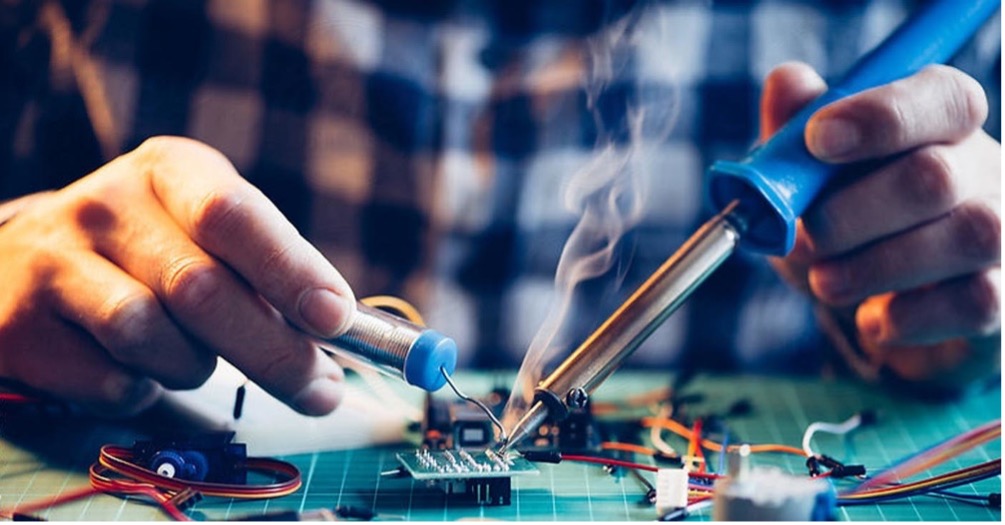
There’s a good reason for that: soldering is a leading technique for making electrical connections and the only practical way to connect most electronic components electrically and mechanically to a board. It’s not hard to learn to solder properly, but it takes practice and patience to master making a good solder joint with solid electrical and mechanical performance rather than a “cold” solder joint, which can mislead you into thinking you have a viable connection when you really don’t.
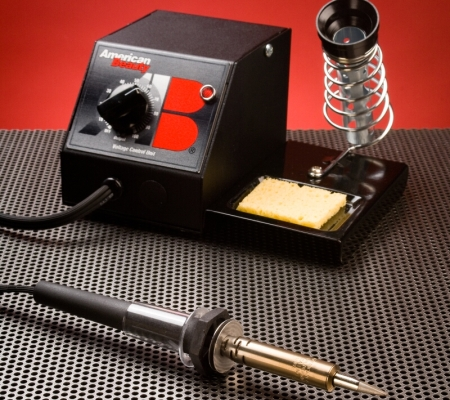
In most of these soldering images, the engineer is using a basic pencil-style soldering iron. That makes sense, as the pencil soldering iron is the one with which most users start out when they are getting into electronics. However, many do-it-yourselfers and most professionals eventually graduate to a temperature-controlled unit, which allows the setting of the desired tip temperature, a useful feature when soldering components, and leads to different thermal masses or sensitivities (Figure 2).
When done properly, a well-made solder joint is reliable, no doubt about it. For many engineers, the act of creating a well-made solder joint, along with the smoke and smell of the melting flux (needed to prevent oxidation), is a mix of artistry and personal satisfaction, admittedly on a small scale.
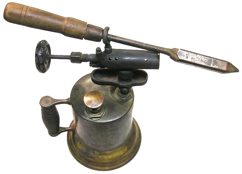
So why is it called a soldering “iron?” The answer is historical: soldering as a metal-joining technology pre-dates electronics. Before our convenient, electrically heated units were available, a soldering iron was just that: an iron placed in a fire to heat up, then pulled out with a working time of about a minute until it cooled down (Figure 3).

These irons were used by experimenters and researchers (the “makers” of their time) as well as plumbers, tinsmiths, and other craftspersons. Serious users would have several of these irons in the fire at the same time, all heating up so there would always be a hot one ready while also eliminating the need to wait for reheating of the one that had cooled.
A larger “iron” head would provide heat for a longer period but could not get into corners or tight spaces, so there was the size-versus-working time tradeoff. Managing this set of irons took attention and time (a helper apprentice was often used here); this challenge gave rise to our cliché about “having too many irons in the fire.”
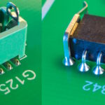
When portable gas-fueled torches were developed, the “in the fire” soldering iron was upgraded to one that could be heated directly by the flame (Figure 4). If you think you have soldering challenges, just remember that the crew laying the first trans-Atlantic telegraph cable in the 1850s used tools such as these to successfully splice and solder the thick undersea cables, all while on a ship on the open sea.
The availability of electricity soon led to pencil-style soldering irons with integral heating elements and the obsoleting of externally heated irons. Even though circuit boards in a production setting are now generally soldered using wave or reflow-soldering technology, there’s still a need for hand soldering for rework, special components, or attaching wires to connectors.
There are some who insist that as today’s electrical engineers spend more of their time at the keyboard, they don’t need to know how to solder. Despite that supposition, the reality is that for many hands-on EEs, soldering by hand is still an important and useful skill. While the traditional pencil-style iron can do the job — whether a basic unregulated unit or a more advanced temperature-controlled unit — it has limitations and shortcomings with respect to placement precision and the risk of causing heat damage to adjacent components or materials such as plastic housings.
Turn dissipation to advantage
Fortunately, there’s a convenient, easy-to-use alternative soldering technique called resistance soldering, which has been available for decades and offers many benefits. It leverages the well-known principle of electrical self-heating to create a very localized “hot spot” that is hot enough to melt the solder and so create a high-quality, reliable solder connection. (The solder itself is the same type as used for pencil-style soldering irons.)
A representative resistance-soldering system can deliver up to 250 watts at 2.8 volts AC to the connection to be soldered (Figure 5). Operation is simple: the current from the system is applied across the joint via a pair of tweezers of the handpiece; the tips of the tweezer are positioned to “straddle” the connection to be made.

The operator steps on a foot pedal, the current flows between the tips, the joint heats, the operator applies the solder, lets it melt and releases the foot pedal. The whole sequence takes only a few seconds, while the heating, which might otherwise damage or melt adjacent components or materials, is nearly non-existent. As the applied voltage across the tips is low — on the order of a few volts — there is no danger of shock to the user or damage to nearby components.
The next part of this article looks at crimped connections and crimping, which is an alternative to soldering for individual cable termination in many cases.
Related Content
What are the five connector contact termination styles used for?
The first undersea transatlantic cable: An audacious project that (eventually) succeeded, Part 1
The first undersea transatlantic cable: An audacious project that (eventually) succeeded, Part 2
Portfolio of crimp termination options simplify on-site assembly
Crimp pins and receptacles for wire termination
New Right Angle Solder Cup Holders
Solder Cup Headers Deliver 25 Percent Height Reduction
New Press-Fit PCB Pins for Plated-through Holes
References
SparkFun, “Working with Wire”
Weidmüller, “Crimping: A permanent connection”
NASA, “Rapid and Verified Crimping for Critical Wiring Needs”


Leave a Reply
You must be logged in to post a comment.